16-59 Adjusted Setpoint
Option: Function:
View value of the adjusted set point according to par.20-29.
27-91 Cascade Reference
Range: Function:
[unit]
*
[0.0 - 0.0] View value of Cascade Reference.
2.15.6. 16-6* Inputs and Outputs
Parameters for reporting the digital and analog IO ports.
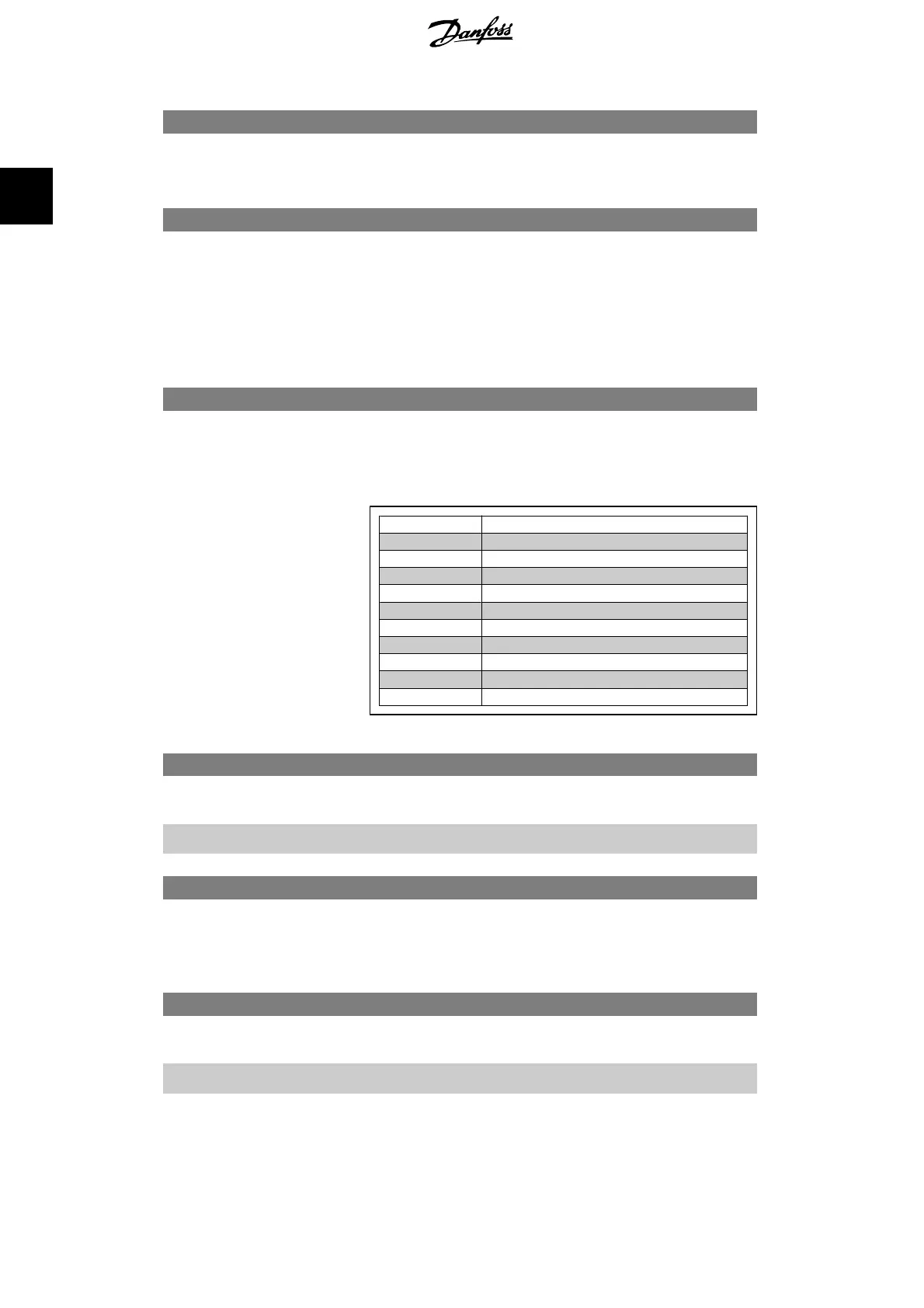
16-60 Digital Input
Range: Function:
0
*
[0 - 63] View the signal states from the active digital inputs. Input 18
corresponds for example to bit 5. '0' = NO signal, '1' = connec-
ted signal.
Bit 0
Digital input term. 33
Bit 1 Digital input term. 32
Bit 2 Digital input term. 29
Bit 3 Digital input term. 27
Bit 4 Digital input term. 19
Bit 5 Digital input term. 18
Bit 6 Digital input term. 37
Bit 7 Digital input GP I/O term. X30/2
Bit 8 Digital input GP I/O term. X30/3
Bit 9 Digital input GP I/O term. X30/4
Bit 10-63 Reserved for future terminals
16-61 Terminal 53 Switch Setting
Option: Function:
[0]
*
Current
[1] Voltage View the setting of input terminal 53. Current = 0; Voltage = 1.
16-62 Analog Input 53
Range: Function:
0.000
*
[0.000 - 0.000] View the actual value at input 53.
16-63 Terminal 54 Switch Setting
Option: Function:
[0]
*
Current
[1] Voltage View the setting of input terminal 54. Current = 0; Voltage = 1.
2. Parameter Description VLT
®
AQUA Drive Programming Guide
166
MG.20.O2.02 - VLT
®
is a registered Danfoss trademark
2
 Loading...


