16-64 Analog Input 54
Range: Function:
0.000
*
[0.000 - 0.000] View the actual value at input 54.
16-65 Analog Output 42 [mA]
Range: Function:
0.000
*
[0.000 - 0.000] View the actual value at output 42 in mA. The value shown re-
flects the selection in par. 06-50.
16-66 Digital Output [bin]
Range: Function:
0
*
[0 - 3] View the binary value of all digital outputs.
16-67 Freq. Input #29 [Hz]
Range: Function:
0
*
[0 - 0] View the actual frequency rate on terminal 29.
16-68 Freq. Input #33 [Hz]
Range: Function:
0
*
[0 - 0] View the actual frequency rate on terminal 33.
16-69 Pulse Output #27 [Hz]
Range: Function:
0
*
[0 - 0] View the actual value on terminal 27 in digital output mode.
16-70 Pulse Output #29 [Hz]
Range: Function:
0
*
[0 - 0] View the actual value of pulses on terminal 29 in digital output
mode.
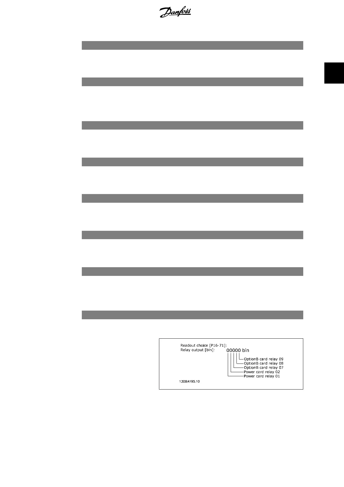
16-71 Relay Output [bin]
Range: Function:
0
*
[0 - 31] View the settings of all relays.
VLT
®
AQUA Drive Programming Guide 2. Parameter Description
MG.20.O2.02 - VLT
®
is a registered Danfoss trademark
167
2
 Loading...


