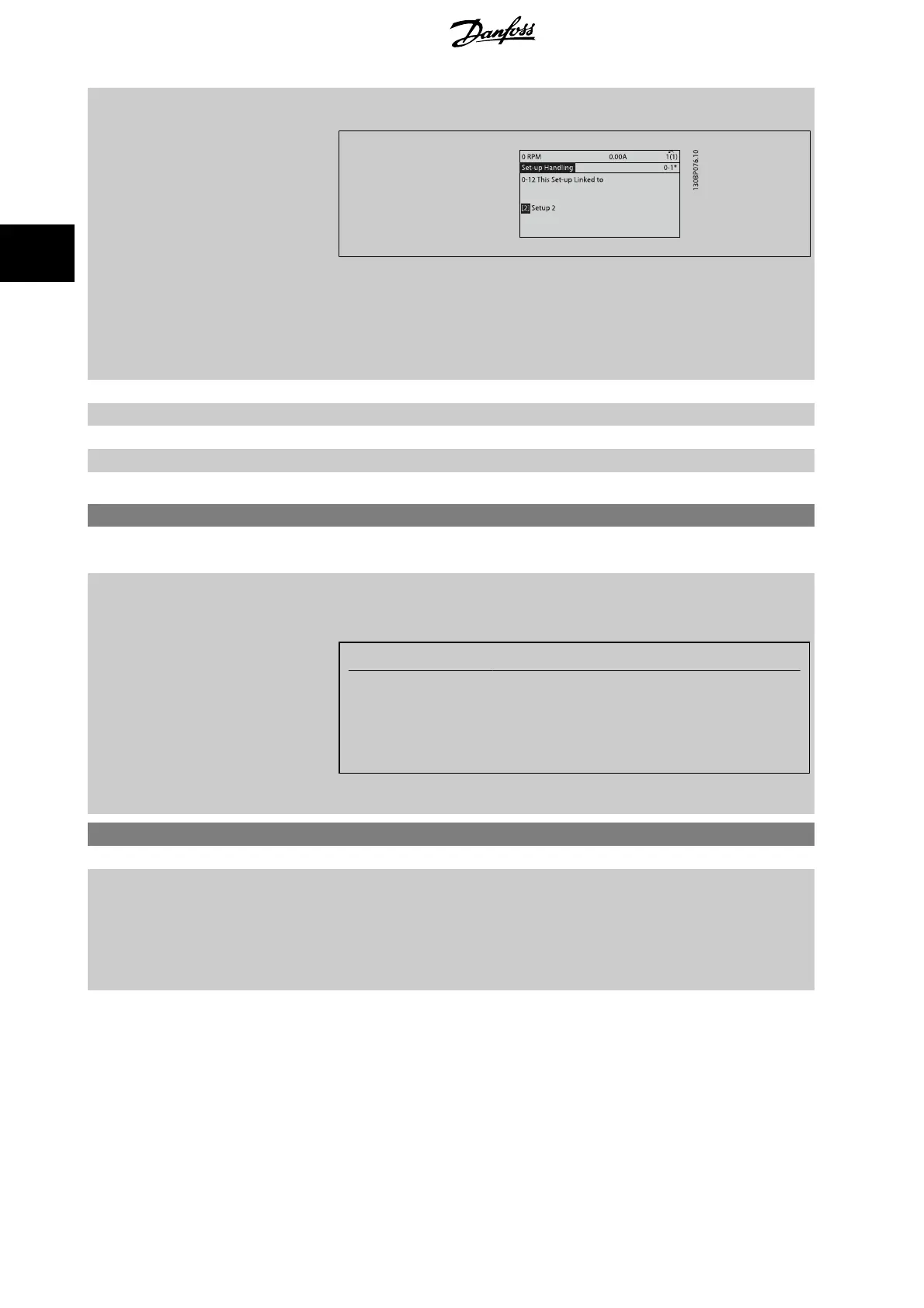
2. While still in Set-up 1, copy Set-up 1 to Set-up 2. Then set par. 0-12
This Set-up Linked to
to
Set-up 2
[2]. This will start the linking process.
After the link is complete, par. 0-13
Readout: Linked Set-ups
will read {1,2} to indicate that all ‘not
changeable during operation’ parameters are now the same in Set-up 1 and Set-up 2. If there are
changes to a ‘not changeable during operation’ parameter, e.g. par. 1-30
Stator Resistance (Rs)
, in
Set-up 2, they will also be changed automatically in Set-up 1. A switch between Set-up 1 and Set-
up 2 during operation is now possible.
[0] * Not linked
[1] Set-up 1
[2] Set-up 2
[3] Set-up 3
[4] Set-up 4
0-13 Readout: Linked Set-ups
Array [5]
Range: Function:
0 N/A* [0 - 255 N/A] View a list of all the set-ups linked by means of par. 0-12
This Set-up Linked to
. The parameter has
one index for each parameter set-up. The parameter value displayed for each index represents
which setups are linked to that parameter setup.
Index LCP value
0 {0}
1 {1,2}
2 {1,2}
3{3}
4 {4}
Table 3.2: Example: Set-up 1 and Set-up 2 are linked
0-14 Readout: Edit Set-ups / Channel
Range: Function:
0* [-2147483648 - 2147483647 ] View the setting of par. 0-11
Edit Set-up
for each of the four different communication channels.
When the number is displayed in hex, as it is in the LCP, each number represents one channel.
Numbers 1-4 represent a set-up number; ‘F’ means factory setting; and ‘A’ means active set-up.
The channels are, from right to left: LCP, FC-bus, USB, HPFB1-5.
Example: The number AAAAAA21h means that the FC bus selected Set-up 2 in par. 0-11
Edit Set-
up
, the LCP selected Set-up 1 and all others used the active set-up.
3.2.4 0-2* LCP Display
Define the variables displayed in the Graphical Local Control Panel.
3 Parameter descriptions FC 300 Programming Guide
34
MG.33.M8.02 - VLT
®
is a registered Danfoss trademark
3

 Loading...


