4.2.2 Receiving the Frequency Converter
When receiving the frequency converter make sure that
the packaging is intact, and be aware of any damage that
might have occurred to the unit during transport. In case
damage has occurred, contact immediately the shipping
company to claim the damage.
4.2.3 Transportation and Unpacking
Before unpacking the frequency converter it is
recommended that it is located as close as possible to the
final installation site.
Remove the box and handle the frequency converter on
the pallet, as long as possible.
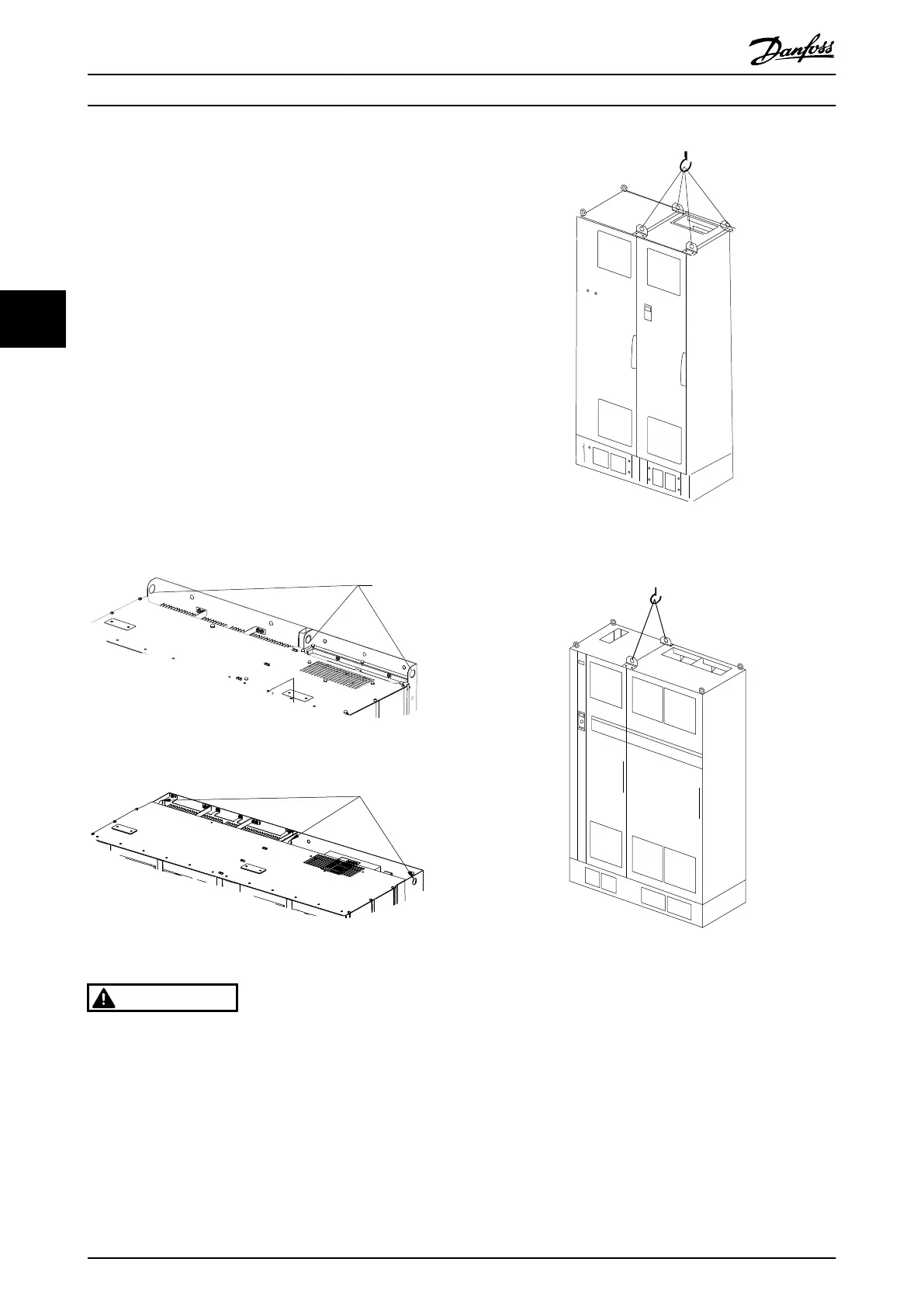
4.2.4
Lifting
Always lift the frequency converter in the dedicated lifting
eyes. For all D and E frames, use a bar to avoid bending
the lifting holes of the frequency converter.
Illustration 4.2 Recommended lifting method, frame sizes D13
Illustration 4.3 Recommended lifting method, frame sizes E9
WARNING
The lifting bar must be able to handle the weight of the
frequency converter. See 4.2.5 Mechanical Dimensions for
the weight of the different frame sizes. Maximum diameter
for bar is 2.5 cm (1 inch). The angle from the top of the
frequency converter to the lifting cable should be 60° or
greater.
Illustration 4.4 Recommended lifting method, frame size F18 -
filter section.
Illustration 4.5 Recommended lifting method, frame size F18 -
drive section.
NOTE
The plinth is provided in the same packaging as the unit
but is not attached to frame size F during shipment. The
plinth is required to allow airflow to the frequency
converter to provide proper cooling. The F frames should
be positioned on top of the plinth in the final installation
location. The angle from the top of the drive to the lifting
cable should be 60° or greater.
In addition to the drawing above a spreader bar is an
acceptable way to lift the F Frame.
How to Install VLT Automation Low Harmonic Drive Operating Instructions
14 MG34O202 - VLT
®
is a registered Danfoss trademark
44

 Loading...


