NOTE
If a retrofit applications requires unequal amount of wires
per phase please consult the factory for requirements and
documentation or use the top/bottom entry side cabinet
option, instruction 177R0097.
4.6.8 Brake Cable Drives with Factory
Installed Brake Chopper Option
(Only standard with letter B in position 18 of typecode).
The connection cable to the brake resistor must be
screened and the max. length from frequency converter to
the DC bar is limited to 25 metres (82 feet).
Terminal No. Function
81, 82 Brake resistor terminals
Table 4.27
The connection cable to the brake resistor must be
screened. Connect the screen by means of cable clamps to
the conductive back plate at the frequency converter and
to the metal cabinet of the brake resistor.
Size the brake cable cross-section to match the brake
torque. See also Brake Instructions, MI90FXYY and MI50SXYY
for further information regarding safe installation.
WARNING
Note that voltages up to 790 V DC, depending on the
supply voltage, may occur on the terminals.
F Frame Requirements
The brake resistor(s) must be connected to the brake
terminals in each inverter module.
4.6.9
Brake Resistor Temperature Switch
Frame size D-E-F
Torque: 0.5-0.6 Nm (5 in-lbs)
Screw size: M3
This input can be used to monitor the temperature of an
externally connected brake resistor. If the connection
between 104 and 106 is removed, the frequency converter
will trip on warning / alarm 27, “Brake IGBT”.
A KLIXON switch must be installed that is `normally closed'
in series with the existing connection on either 106 or 104.
Any connection to this terminal must be double insulated
to high voltage to maintain PELV.
Normally closed: 104-106 (factory installed jumper).
Terminal No.
Function
106, 104, 105 Brake resistor temperature switch.
Table 4.28
CAUTION
If the temperature of the brake resistor gets too high and
the thermal switch drops out, the frequency converter will
stop braking. The motor will start coasting.
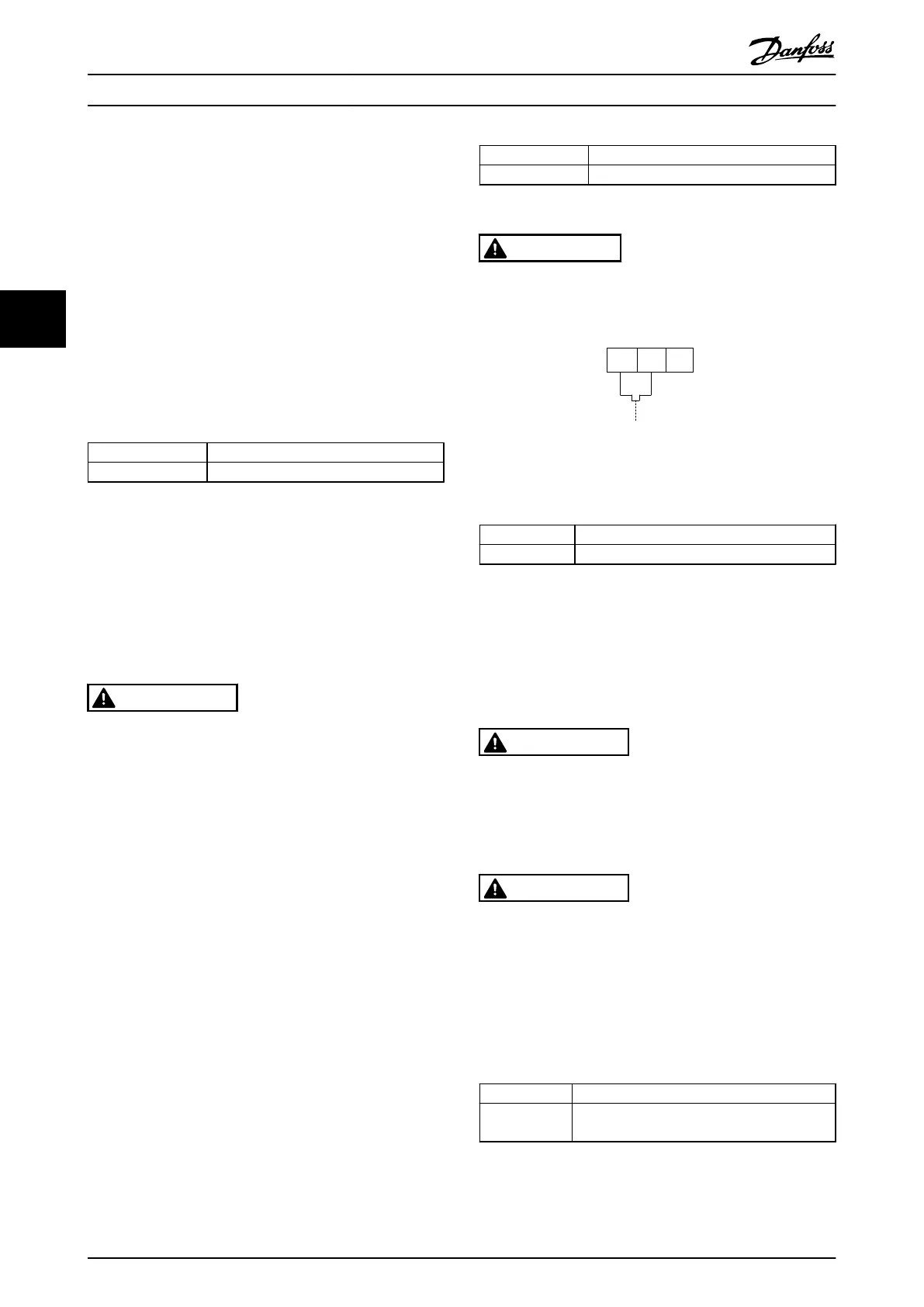
175ZA877.10
106
NC
104
C
105
NO
Illustration 4.31
4.6.10 Load Sharing
Terminal No. Function
88, 89 Loadsharing
Table 4.29
The connection cable must be screened and the max.
length from the frequency converter to the DC bar is
limited to 25 metres (82 feet).
Load sharing enables linking of the DC intermediate
circuits of several frequency converters.
WARNING
Please note that voltages up to 1099 VDC may occur on
the terminals.
Load Sharing calls for extra equipment and safety consid-
erations. For further information, see load sharing
Instructions MI50NXYY.
WARNING
Please note that mains disconnect may not isolate the
frequency converter due to DC link connection
4.6.11 Mains Connection
Mains must be connected to terminals 91, 92 and 93
located on the far left of the unit. Earth is connected to
the terminal to the right of terminal 93.
Terminal No.
Function
91, 92, 93
94
Mains R/L1, S/L2, T/L3
Earth
Table 4.30
How to Install VLT Automation Low Harmonic Drive Operating Instructions
46 MG34O202 - VLT
®
is a registered Danfoss trademark
44

 Loading...


