4.8 Electrical Installation - Additional
4.8.1 Electrical Installation, Control Cables
1
DC bus
Switch Mode
Power Supply
Motor
Analog Output
Interface
relay1
relay2
(PNP) = Source
(NPN) = Sink
ON=Terminated
OFF=Open
Brake
resistor
130BB450.10
91 (L1)
92 (L2)
93 (L3)
PE
88 (-)
89 (+)
50 (+10 V OUT)
53 (A IN)
54 (A IN)
55 (COM A IN)
0/4-20 mA
12 (+24V OUT)
13 (+24V OUT)
37 (D IN)
18 (D IN)
20 (COM D IN)
10Vdc
15mA 130/200mA
+ - + -
(U) 96
(V) 97
(W) 98
(PE) 99
(COM A OUT) 39
(A OUT) 42
(P RS-485) 68
(N RS-485) 69
(COM RS-485) 61
0V
5V
S801
0/4-20 mA
RS-485
RS-485
03
+10Vdc
-10Vdc -
+10Vdc
+10Vdc
0/4-20 mA
-10Vdc -
240Vac, 2A
24Vdc
02
01
05
04
06
240Vac, 2A
24V (NPN)
0V (PNP)
0V (PNP)
24V (NPN)
19 (D IN)
24V (NPN)
0V (PNP)
27
24V
0V
(D IN/OUT)
0V (PNP)
24V (NPN)
(D IN/OUT)
0V
24V
29
24V (NPN)
0V (PNP)
0V (PNP)
24V (NPN)
33 (D IN)
32 (D IN)
1 2
ON
S201
ON
21
S202
ON/I=0-20mA
OFF/U=0-10V
95
400Vac, 2A
P 5-00
21
ON
S801
(R+) 82
(R-) 81
*
*
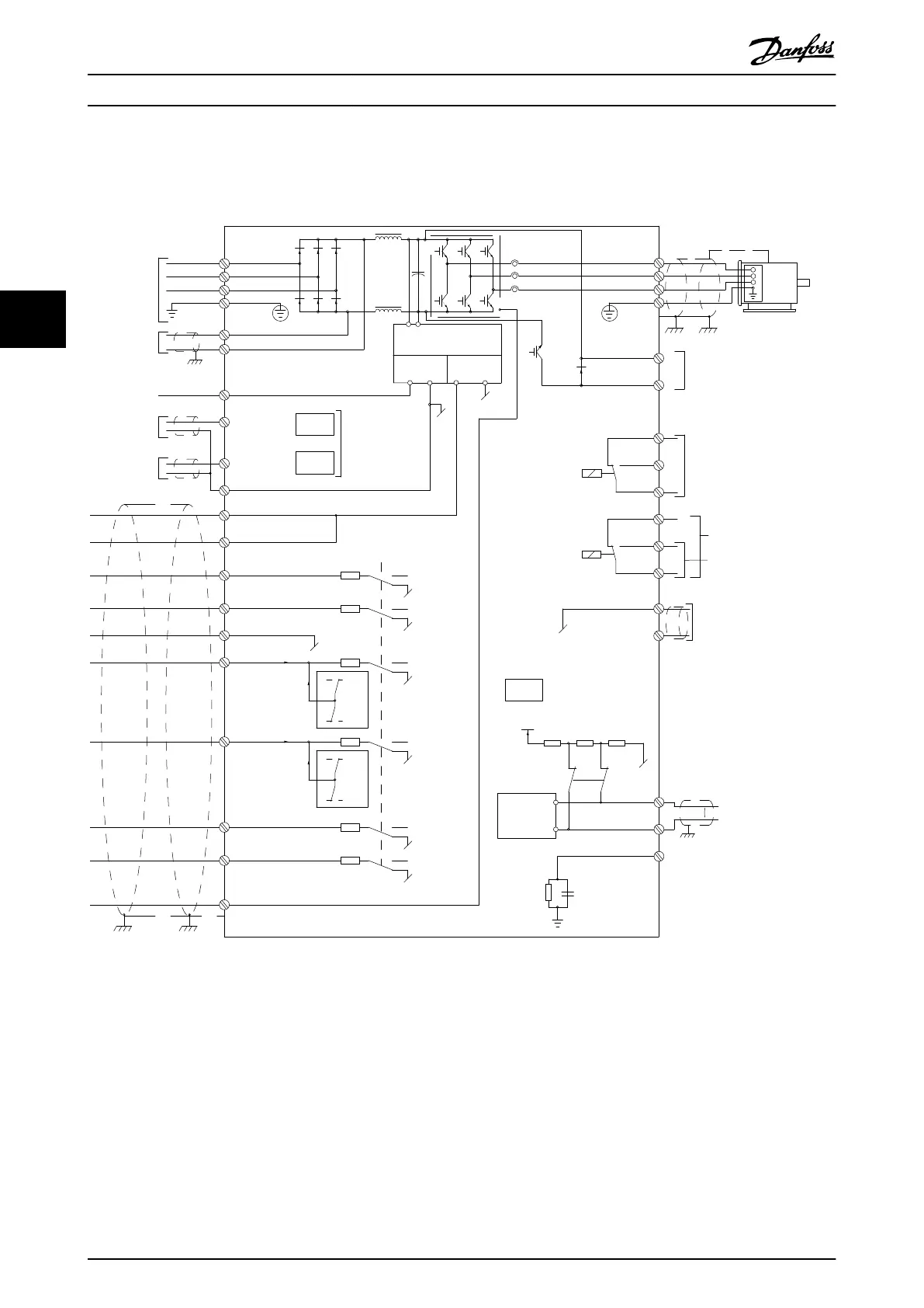
Illustration 4.39 Diagram showing all electrical terminals without options.
1: Connection to filter
Terminal 37 is the input to be used for Safe Stop. For instructions on Safe Stop installation please refer to the section Safe Stop Instal-
lation in the frequency converter Design Guide. See also sections Safe Stop and Safe Stop Installation.
Very long control cables and analogue signals may in rare
cases and depending on installation result in 50/60 Hz
earth loops due to noise from mains supply cables.
If this occurs, it may be necessary to break the screen or
insert a 100 nF capacitor between screen and chassis.
The digital and analog inputs and outputs must be
connected separately to the control cards of the unit (both
filter and drive, terminal 20, 55, 39) to avoid earth currents
from both groups to affect other groups. For example,
switching on the digital input may disturb the analog
input signal.
How to Install VLT Automation Low Harmonic Drive Operating Instructions
54 MG34O202 - VLT
®
is a registered Danfoss trademark
44

 Loading...


