Example: The frequency converter trips when the motor
temperature is too high.
Parameter set-up:
Set 1-90 Motor Thermal Protection to Thermistor Trip [2]
Set 1-93 Thermistor Source to Digital Input [6]
PTC / Thermistor
R
OFF
ON
<800 Ω
+10V
130BA152.10
>2.7 kΩ
12 13 18 37322719 29 33 20
5550
39 42 53 54
Illustration 6.3
Using an analog input and 10 V as power supply:
Example: The frequency converter trips when the motor
temperature is too high.
Parameter set-up:
Set 1-90 Motor Thermal Protection to Thermistor Trip [2]
Set 1-93 Thermistor Source to Analog Input 54 [2]
555039 42 53 54
R
<3.0 k Ω
>3.0 k Ω
+10V
130BA153.11
PTC / Thermistor
OFF
ON
Illustration 6.4
Input
Digital/analog
Supply Voltage Threshold
Cut-out Values
Digital 10 V
< 800 Ω - > 2.7 kΩ
Analog 10 V
< 3.0 kΩ - > 3.0 kΩ
Table 6.2
NOTE
Check that the chosen supply voltage follows the specifi-
cation of the used thermistor element.
6.1.3.2 KTY Sensor Connection
(FC 302 only)
KTY sensors are used especially in Permanent Magnet
Servo Motors (PM motors) for dynamic adjusting of motor
parameters as stator resistance (1-30 Stator Resistance (Rs))
for PM motors and also rotor resistance (1-31 Rotor
Resistance (Rr)
) for asynchronous motors, depending on
winding temperature. The calculation is:
Rs
=
Rs
20°
C
x
(1 + α
cu
x
Δ
T
) Ω where α
cu
= 0.00393
KTY sensors can be used for motor protecting (1-97 KTY
Threshold level).
FC 302 can handle three types of KTY sensors, defined in
1-95 KTY Sensor Type. The actual sensor temperature can be
read out from 16-19 KTY sensor temperature.
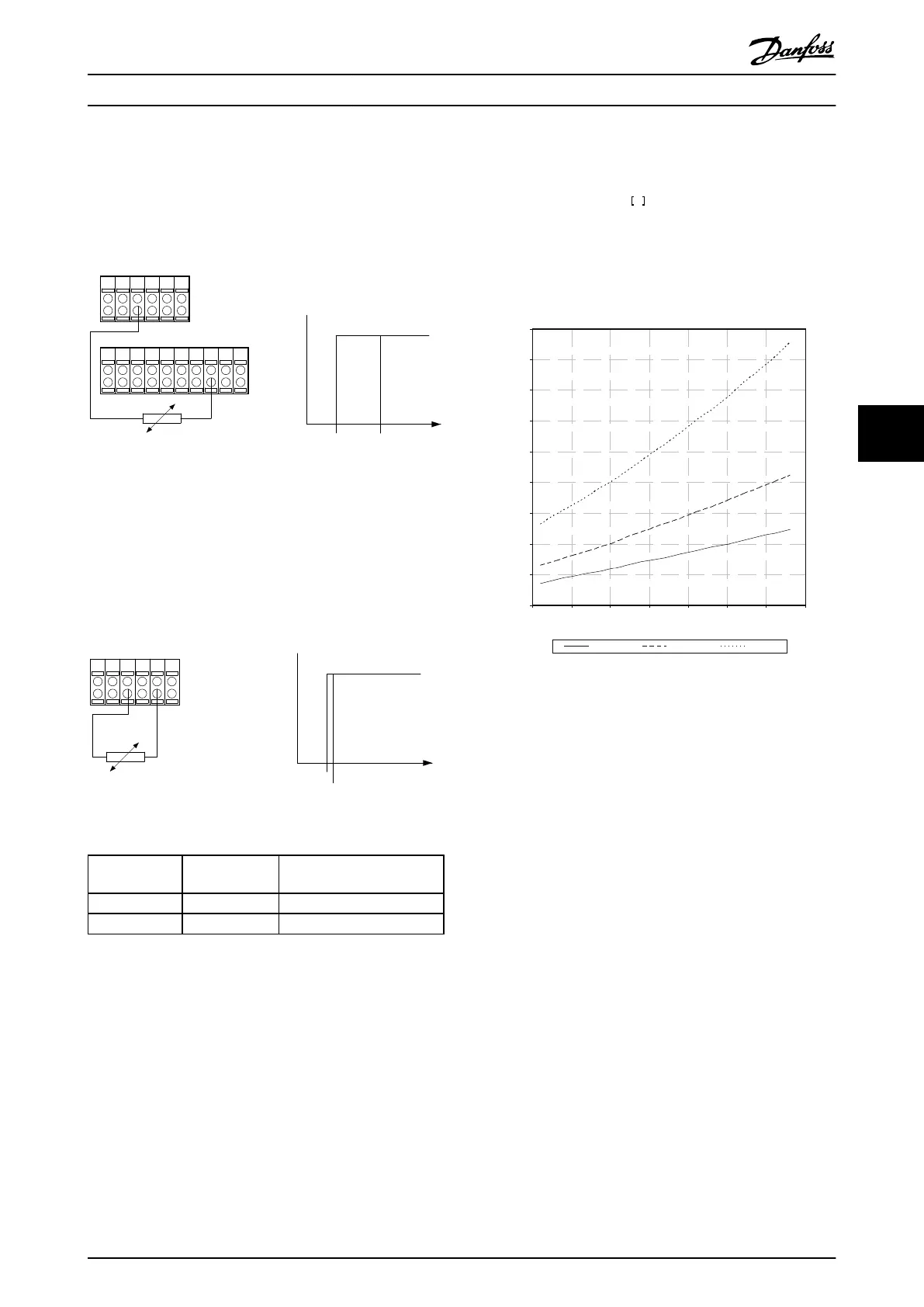
0
500
1000
1500
2000
2500
3000
3500
4000
4500
-25 0 25 50 75 100 125 150
Temperature [°C]
Resistance [Ohm]
KTY type 1 KTY type 2 KTY type 3
Illustration 6.5 KTY type selection
KTY Sensor 1: KTY 84-1 with 1 kΩ at 100° C
KTY Sensor 2: KTY 81-1, KTY 82-1 with 1 kΩ at 25° C
KTY Sensor 3: KTY 81-2, KTY 82-2 with 2 kΩ at 25° C
NOTE
If the temperature of the motor is utilized through a
thermistor or KTY sensor the PELV is not complied with in
case of short circuits between motor windings and sensor.
In order to comply with PELV the sensor must be extra
isolated.
6.1.3.3 ETR
The calculations estimate the need for a lower load at
lower speed due to less cooling from the fan incorporated
in the motor.
How to Programme the Low Ha... VLT Automation Low Harmonic Drive Operating Instructions
MG34O202 - VLT
®
is a registered Danfoss trademark 71
6
6

 Loading...


