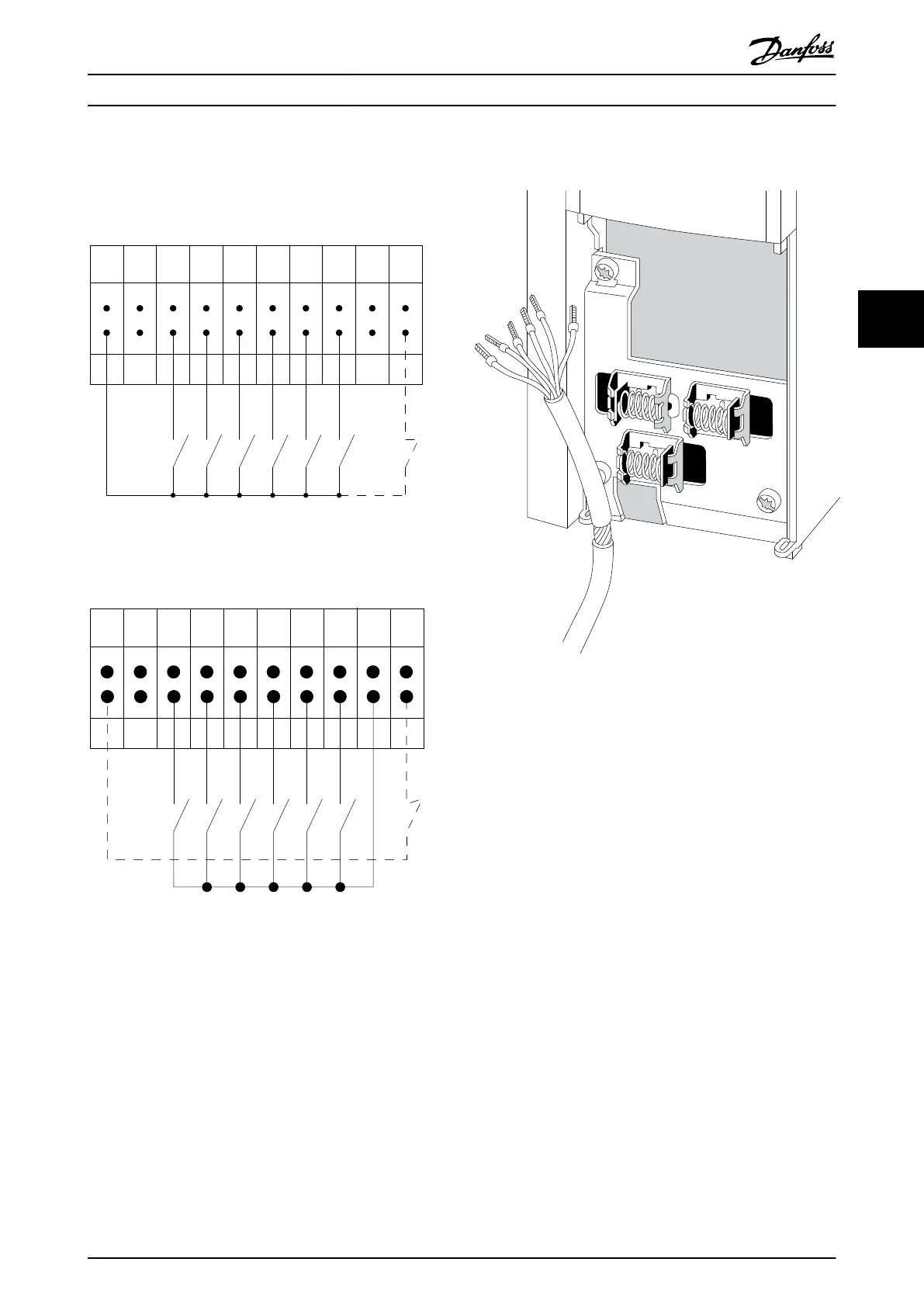
Input polarity of control terminals
12 13 18 19 27 29 32 33 20 37
+24 VDC
0 VDC
130BT106.10
PNP (Source)
Digital input wiring
Illustration 4.40
NPN (Sink)
Digital input wiring
12 13 18 19 27 29 32 33 20 37
+24 VDC
0 VDC
130BT107.11
Illustration 4.41
NOTE
To comply with EMC emission specifications, screened/
armoured cables are recommended. If an unscreened/
unarmoured cable is used, see 4.6.13 Power and Control
Wiring for Unscreened Cables. If unscreened control cables
are used, it is recommended to use ferrite cores to
improve EMC performance.
Illustration 4.42
Connect the wires as described in the Operating
Instruction for the frequency converter. Remember to
connect the shields in a proper way to ensure optimum
electrical immunity.
4.8.2
Switches S201, S202, and S801
Switches S201 (A53) and S202 (A54) are used to select a
current (0-20mA) or a voltage (-10 to 10V) configuration of
the analog input terminals 53 and 54 respectively.
Switch S801 (BUS TER.) can be used to enable termination
on the RS-485 port (terminals 68 and 69).
See Illustration 4.39
Default setting:
S201 (A53) = OFF (voltage input)
S202 (A54) = OFF (voltage input)
S801 (Bus termination) = OFF
How to Install VLT Automation Low Harmonic Drive Operating Instructions
MG34O202 - VLT
®
is a registered Danfoss trademark 55
4 4

 Loading...


