14-50 RFI Filter
This parameter is only available for FC 302. It is not relevant toFC
301 due to different design and shorter motor cables.
Option: Function:
[0] Off
Select [0] Off if the frequency converter is fed by an
isolated mains source (IT mains).
If a filter is used, select Off [0] during charging to
prevent a high leakage current making the RCD
switch.
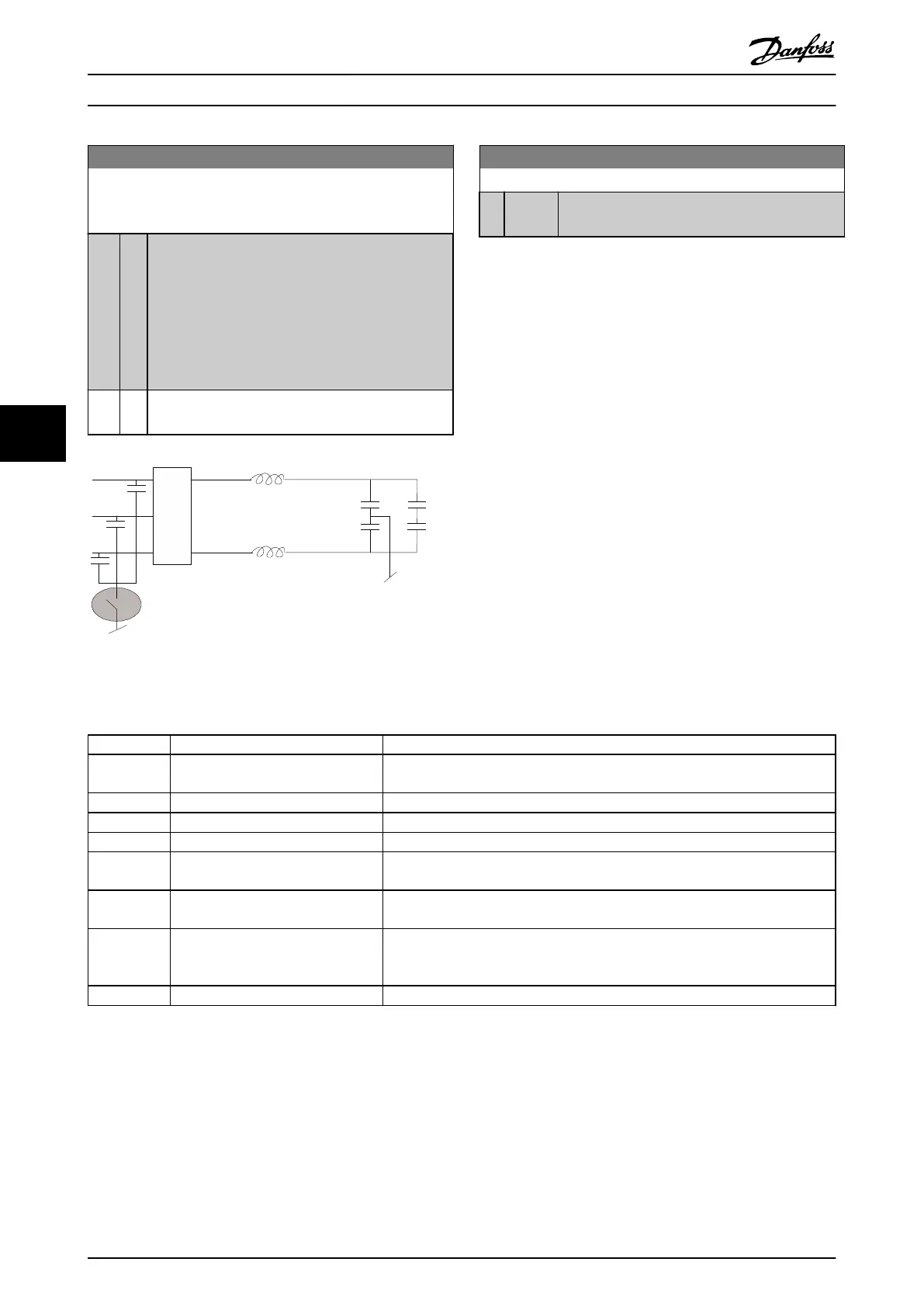
In this mode, the internal RFI filter capacitors between
chassis and the mains RFI filter circuit are cut-out to
reduce the ground capacity currents.
[1] * On
Select [1] On to ensure that the frequency converter
complies with EMC standards.
Illustration 6.14
15-43 Software Version
Range: Function:
0 * [0 - 0 ] View the combined SW version (or ‘package
version’) consisting of power SW and control SW.
6.2 How to Programme the Active Filter
The factory settings for the filter part of the Low Harmonic
Drive are chosen for optimal operation with a minimum of
additional programming. All CT-values, as well as
frequency, voltage levels and other values directly linked
to the drive configuration are pre-set.
It is not recommended to change any other parameters
influencing the filter operation. However, selection of read-
outs and what information to be displayed on the LCP
status lines can be made to fit individual preferences.
To set up the filter two steps are necessary:
•
Change the nominal voltage in 300-10 Active Filter
Nominal Voltage
•
Make sure the filter is in auto mode (press [Auto
On])
Overview of parameter groups for the filter part
Group Title Function
0-** Operation / Display Parameters related to the fundamental functions of the filter, function of the LCP
buttons and configuration of the LCP display.
5-** Digital In/Out Parameter group for configuring the digital inputs and outputs.
8-** Communication and Options Parameter group for configuring communications and options.
14-** Special Functions Parameter group for configuring special functions.
15-** Unit Information Parameter group containing active filter information such as operating data,
hardware configuration and software versions.
16-** Data Readouts Parameter group for data read-outs, e.g. actual references, voltages, control, alarm,
warning and status words.
300-** AF Settings
Parameter group for setting the Active Filter. Apart from par. 300-10, Active Filter
Nominal Voltage, it is not recommended to change the settings of this parameter
group
301-** AF Readouts Parameter group for the filter readouts.
Table 6.12 Parameter groups
A list of all parameters accessible from the filter LCP can
be found in the section Parameter Options - Filter. A more
detailed description of the active filter parameters can be
found in the VLT Active Filter AAF00x Operating Instructions,
MG90VXYY
6.2.1 Using the Low Harmonic Drive in NPN
Mode
The default setting for 5-00 Digital I/O Mode is PNP mode.
If NPN mode is desired, it is necessary to change the
wiring in the filter part of the Low Harmonic Drive. Before
changing the setting in 5-00 Digital I/O Mode to NPN
How to Programme the Low Ha... VLT Automation Low Harmonic Drive Operating Instructions
88 MG34O202 - VLT
®
is a registered Danfoss trademark
6
6

 Loading...


