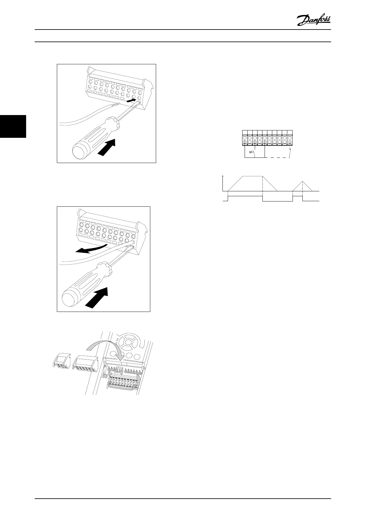
3. Insert the cable in the adjacent circular hole.
4. Remove the screwdriver. The cable is now
mounted in the terminal.
To remove the cable from the terminal:
1.
Insert a screw driver
1)
in the square hole.
2. Pull out the cable.
1)
Max. 0.4 x 2.5 mm
Illustration 4.34
4.7 Connection Examples for Control of
Motor with External Signal Provider
NOTE
The following examples refer only to the frequency
converter control card (right LCP), not the filter.
4.7.1 Start/Stop
Terminal 18 = 5-10 Terminal 18 Digital Input [8] Start
Terminal 27 = 5-12 Terminal 27 Digital Input [0] No
operation (Default coast inverse)
Terminal 37 = Safe stop
12 13 18 37
130BA155.12
322719 29 33 20
P 5-12 [0]
P 5-10 [8]
Start/Stop
+24V
Speed
Safe Stop
Start/Stop
[18]
Illustration 4.35
How to Install VLT Automation Low Harmonic Drive Operating Instructions
52 MG34O202 - VLT
®
is a registered Danfoss trademark
44

 Loading...


