4) The typical power loss is at nominal load
conditions and expected to be within +/-15%
(tolerence relates to variety in voltage and cable
conditions). Values are based on a typical motor
efficiency (eff2/eff3 border line). Motors with
lower efficiency will also add to the power loss in
the frequency converter and opposite. If the
switching frequency is increased comed to the
default setting, the power losses may rise signifi-
cantly.LCP and typical control card power
consumptions are included. Further options and
customer load may add up to 30 W to the losses.
(Though typical only 4 W extra for a fully loaded
control card, or options for slot A or slot B, each).
Although measurements are made with state of
the art equipment, some measurement
inaccuracy must be allowed for (+/-5%).
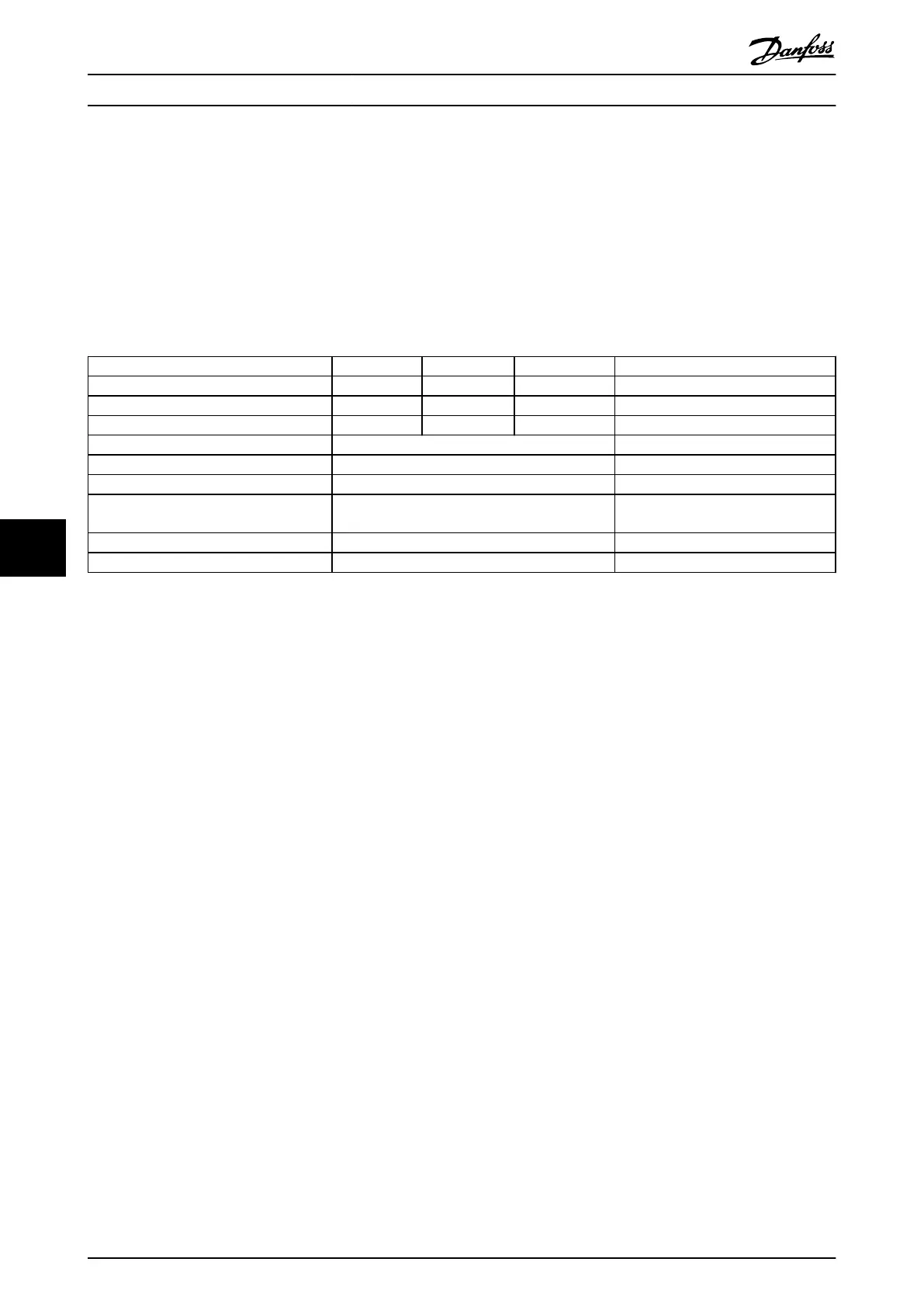
8.2 Filter Specifications
Frame size D E F
Voltage [V] 380-480 380-480 380-480
Current, RMS [A] 120 210 330 Nominal value
Peak Current [A] 340 595 935 Amplitude value of the current
RMS overload [%] No Overload 60 s in 10 min
Response time [ms] <0.5
Settling time - reactive current control [ms] <40
Settling time - harmonic current control
(filtering) [ms]
<20
Overshoot - reactive current control [%] <20
Overshoot - harmonic current control [%] <10
Table 8.4 Power Ranges (LHD with AF)
General Specifications VLT Automation Low Harmonic Drive Operating Instructions
146 MG34O202 - VLT
®
is a registered Danfoss trademark
88

 Loading...


