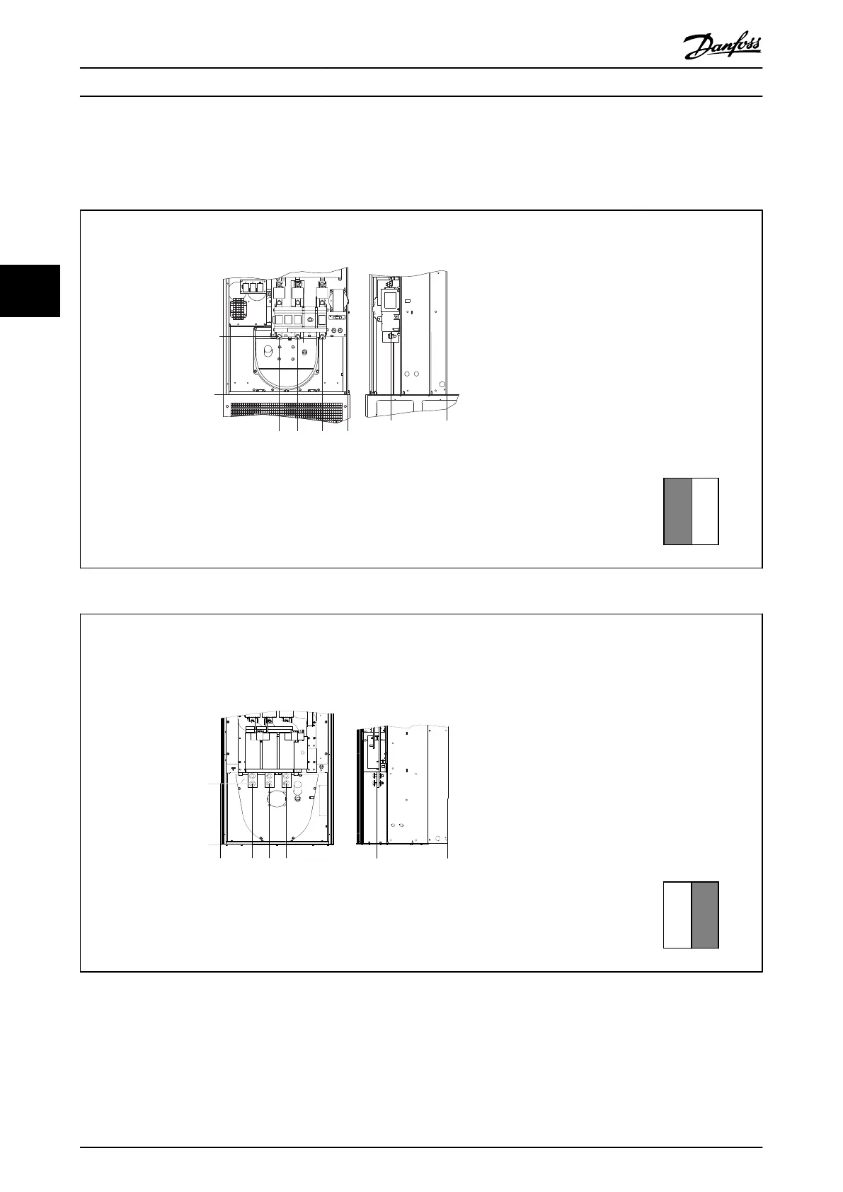
4.3.3 Terminal Locations - Frame Size D13
Take the following position of the terminals into consid-
eration when designing the cable access.
3X 276,87
[10.9]
0
[.0]
267,4
[10.5]
0
[.0]
120,8
[4.8]
236,8
[9.3]
0
[.0]
324,8
[12.8]
130BB723.10
Illustration 4.13 Terminal locations - mains cables
Section shown
↓
1 2
Table 4.3
323,9
[12,8]
0
[0]
0
[0]
0
[0]
380,7
[15]
169,7
[6,6]
258,7
[10,2]
348,7
[13,7]
130BB724.10
Illustration 4.13 Terminal locations E9- drive
Section shown
↓
1 2
Table 4.4
Be aware that the power cables are heavy and hard to
bend. Consider the optimum position of the frequency
converter for ensuring easy installation of the cables.
NOTE
All D frames are available with standard input terminals or
disconnect switch
How to Install VLT Automation Low Harmonic Drive Operating Instructions
22 MG34O202 - VLT
®
is a registered Danfoss trademark
44

 Loading...


