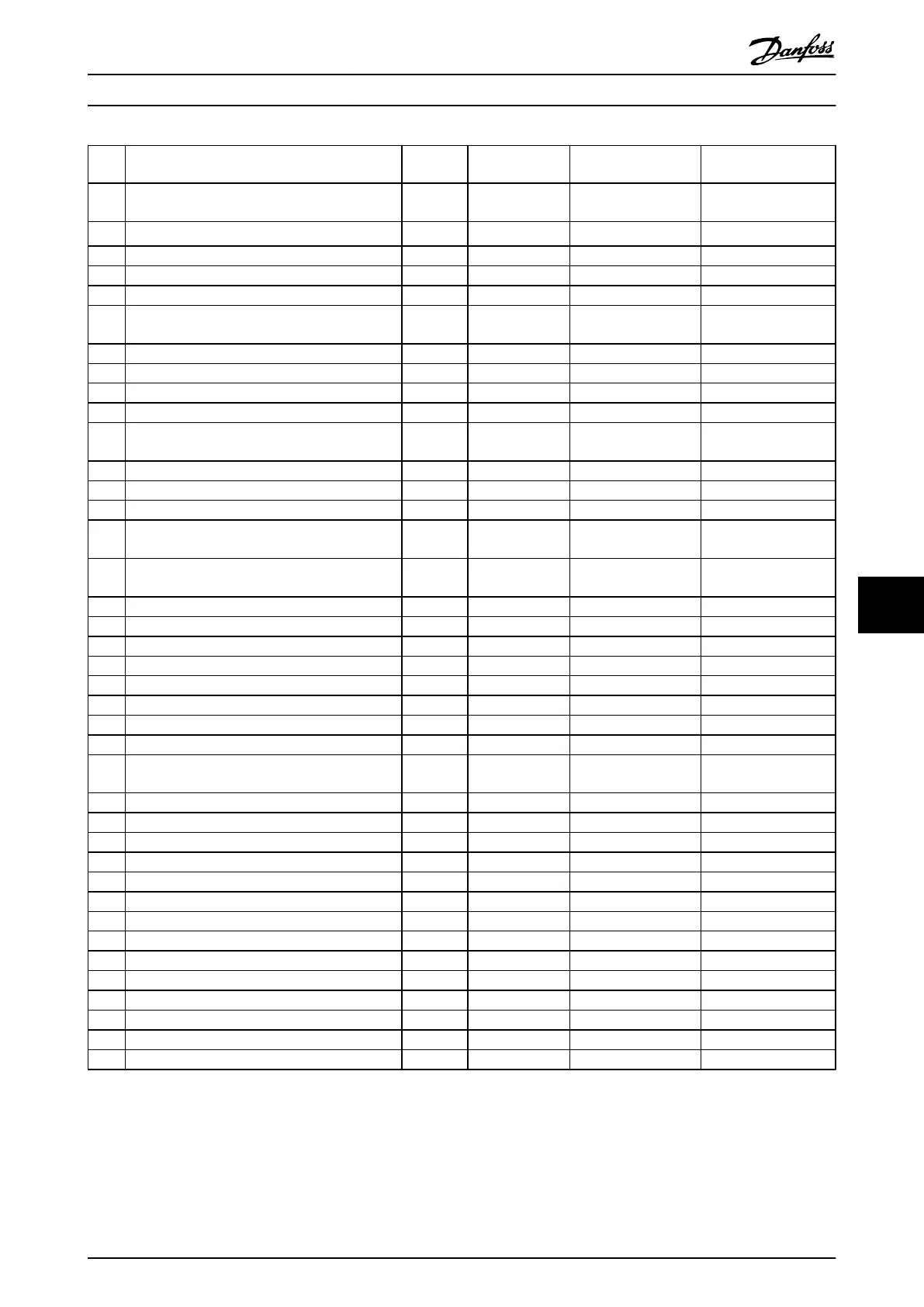
No. Description Warning Alarm/Trip Alarm/Trip Lock Parameter
Reference
63 Mechanical Brake Low (X) 2-20 Release Brake
Current
64 Voltage Limit X
65 Control Board Over-temperature X X X
66 Heat sink Temperature Low X
67 Option Configuration has Changed X
68 Safe Stop (X)
(X)
1)
5-19 Terminal 37 Safe
Stop
69 Pwr. Card Temp X X
70 Illegal FC configuration X
71 PTC 1 Safe Stop
72 Dangerous failure
73 Safe Stop Auto Restart (X) (X) 5-19 Terminal 37 Safe
Stop
74 PTC Thermistor X
75 Illegal Profile Sel. X
76 Power Unit Setup X
77 Reduced power mode X 14-59 Actual Number of
Inverter Units
78 Tracking Error (X) (X) 4-34 Tracking Error
Function
79 Illegal PS config X X
80 Drive Initialized to Default Value X
81 CSIV corrupt X
82 CSIV parameter error X
83 Illegal Option Combination X
84 No Safety Option X
88 Option Detection X
89 Mechanical Brake Sliding X
90 Feedback Monitor (X) (X) 17-61 Feedback Signal
Monitoring
91 Analog input 54 wrong settings X S202
163 ATEX ETR cur.lim.warning X
164 ATEX ETR cur.lim.alarm X
165 ATEX ETR freq.lim.warning X
166 ATEX ETR freq.lim.alarm X
243 Brake IGBT X X X
244 Heatsink temp X X X
245 Heatsink sensor X X
246 Pwr.card supply X
247 Pwr.card temp X X
248 Illegal PS config X
249 Rect. low temp. X
250 New spare parts X
251 New Type Code X X
Table 9.1 Alarm/Warning code list
(X) Dependent on parameter
1) Can not be Auto reset via 14-20 Reset Mode
A trip is the action when an alarm has appeared. The trip
will coast the motor and can be reset by pressing [Reset]
or make a reset by a digital input (parameter group 5-1*
[1]). The origin event that caused an alarm cannot damage
the frequency converter or cause dangerous conditions. A
trip lock is an action when an alarm occurs, which may
cause damage to thefrequency converter or connected
Troubleshooting VLT Automation Low Harmonic Drive Operating Instructions
MG34O202 - VLT
®
is a registered Danfoss trademark 149
9 9

 Loading...


