90
80
70
60
50
40
30
20
10
0
0 0.5 4.9 13 27.3 45.9 66 89.3 115.7 147
(%)
(Pa)
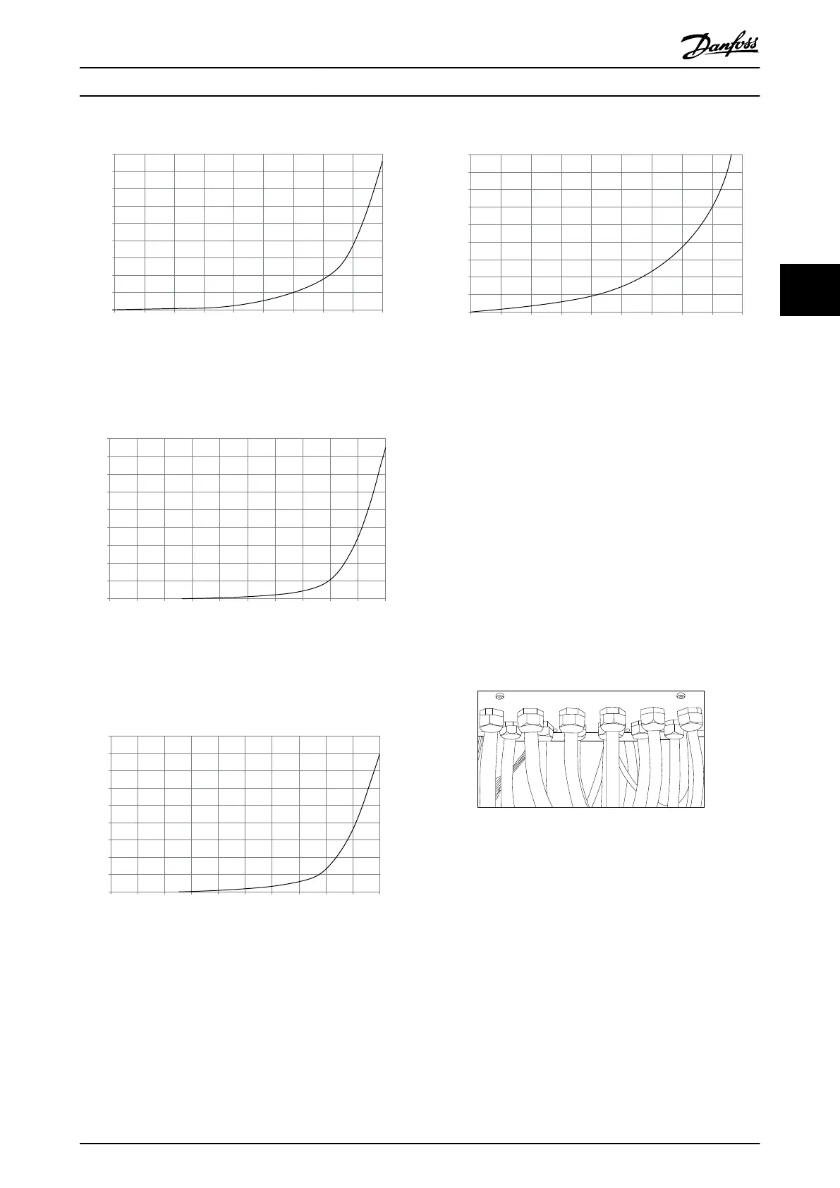
Pressure Increase
Drive Derating
130BB007.10
Illustration 4.14 D frame Derating vs. Pressure Change
Drive air flow: 450 cfm (765 m
3
/h)
90
80
70
60
50
40
30
20
10
0
(%)
Drive Derating
0 0 0.1 3.6 9.8 21.5 43.4 76 237.5 278.9
(Pa)
Pressure Change
130BB010.10
147.1
Illustration 4.15 E frame Derating vs. Pressure Change (Small
Fan), P315
Drive air flow: 650 cfm (1105 m
3
/h)
90
80
70
60
50
40
30
20
10
0
(%)
Drive Derating
0 0.2 0.6 2.2 5.8 11.4 18.1 30.8 152.8 210.8
(Pa)
Pressure Change
130BB011.10
69.5
Illustration 4.16 E frame Derating vs. Pressure Change (Large
Fan) P355-P450
Drive air flow: 850 cfm (1445 m
3
/h)
90
80
70
60
50
40
30
20
10
0
(%)
Drive Derating
0 25 50 75 100 125 150 175 225
130BB190.10
200
Pressure Change
Illustration 4.17 F frame Derating vs. Pressure Change
Drive air flow: 580 cfm (985 m
3
/h)
4.3.7
Gland/Conduit Entry - IP21 (NEMA 1)
and IP54 (NEMA12)
Cables are connected through the gland plate from the
bottom. Remove the plate and plan where to place the
entry for the glands or conduits. Prepare holes in the
marked area on the drawing.
NOTE
The gland plate must be fitted to the frequency converter
to ensure the specified protection degree, as well as
ensuring proper cooling of the unit. If the gland plate is
not mounted, the frequency converter may trip on Alarm
69, Pwr. Card Temp
Illustration 4.18 Example of proper installation of the gland
plate.
How to Install VLT Automation Low Harmonic Drive Operating Instructions
MG34O202 - VLT
®
is a registered Danfoss trademark 29
4 4

 Loading...


