WARNING
HIGH VOLTAGE
Drives contain high voltage when connected to AC mains
input, DC supply, or load sharing. Failure to perform
installation, start-up, and maintenance by qualied
personnel can result in death or serious injury.
•
Only qualied personnel must perform instal-
lation, start-up, and maintenance.
•
Before performing any service or repair work,
use an appropriate voltage measuring device to
make sure that there is no remaining voltage on
the drive.
Troubleshooting
•
Remove the power from the drive and check
motor phase V.
ALARM 32, Motor phase W missing
Motor phase W between the drive and the motor is
missing.
WARNING
HIGH VOLTAGE
Drives contain high voltage when connected to AC mains
input, DC supply, or load sharing. Failure to perform
installation, start-up, and maintenance by qualied
personnel can result in death or serious injury.
•
Only qualied personnel must perform instal-
lation, start-up, and maintenance.
•
Before performing any service or repair work,
use an appropriate voltage measuring device to
make sure that there is no remaining voltage on
the drive.
Troubleshooting
•
Remove the power from the drive and check
motor phase W.
ALARM 33, Inrush fault
Too many power-ups have occurred within a short time
period.
Troubleshooting
•
Let the unit cool to operating temperature.
•
Check potential DC-link fault to ground.
WARNING/ALARM 34, Fieldbus communication fault
The eldbus on the communication option card is not
working.
WARNING/ALARM 35, Option fault
An option alarm is received. The alarm is option-specic.
The most likely cause is a power-up or a communication
fault.
WARNING/ALARM 36, Mains failure
This warning/alarm is only active if the supply voltage to
the drive is lost and parameter 14-10 Mains Failure is not
set to [0] No function.
Troubleshooting
•
Check the fuses to the drive and mains supply to
the unit.
ALARM 37, Phase imbalance
There is a current imbalance between the power units.
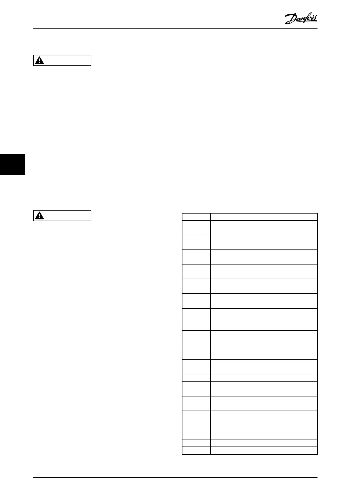
ALARM 38, Internal fault
When an internal fault occurs, a code number dened in
Table 6.4 is shown.
Troubleshooting
•
Cycle power.
•
Check that the option is properly installed.
•
Check for loose or missing wiring.
It may be necessary to contact the Danfoss supplier or
service department. Note the code number for further
troubleshooting directions.
Number Text
0 The serial port cannot be initialized. Contact the
Danfoss supplier or Danfoss service department.
256–258 The power EEPROM data is defective or too old.
Replace the power card.
512–519 Internal fault. Contact the Danfoss supplier or
Danfoss service department.
783 Parameter value outside of minimum/maximum
limits.
1024–1284 Internal fault. Contact the Danfoss supplier or
Danfoss service department.
1299 The option software in slot A is too old.
1300 The option software in slot B is too old.
1302 The option software in slot C1 is too old.
1315 The option software in slot A is not supported/
allowed.
1316 The option software in slot B is not supported/
allowed.
1318 The option software in slot C1 is not supported/
allowed.
1379–2819 Internal fault. Contact the Danfoss supplier or
Danfoss service department.
1792 Hardware reset of digital signal processor.
1793 Motor-derived parameters not transferred correctly
to the digital signal processor.
1794 Power data not transferred correctly at power-up
to the digital signal processor.
1795 The digital signal processor has received too many
unknown SPI telegrams. This situation can occur
due to poor EMC protection or improper
grounding.
1796 RAM copy error.
2561 Replace the control card.
Troubleshooting VLT® AutomationDrive FC 361
186 Danfoss A/S © 03/2019 All rights reserved. MG06J202
6
6

 Loading...


