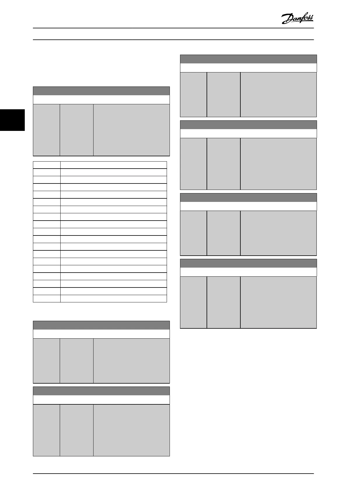
4.6.6 5-9* Bus-controlled
This parameter group selects digital and relay outputs via a
eldbus setting.
5-90 Digital & Relay Bus Control
Range: Function:
0* [0 -
2147483647]
This parameter holds the state of
the digital outputs and relays that
is controlled by bus.
A logical 1 indicates that the
output is high or active.
A logical 0 indicates that the
output is low or inactive.
Bit 0 Digital output terminal 27
Bit 1 Digital output terminal 29
Bit 2 Digital output terminal X 30/6
Bit 3 Digital output terminal X 30/7
Bit 4 Relay 1 output terminal
Bit 5 Relay 2 output terminal
Bit 6 Option B relay 1 output terminal
Bit 7 Option B relay 2 output terminal
Bit 8 Option B relay 3 output terminal
Bit 9–15 Reserved for future terminals
Bit 16 Option C relay 1 output terminal
Bit 17 Option C relay 2 output terminal
Bit 18 Option C relay 3 output terminal
Bit 19 Option C relay 4 output terminal
Bit 20 Option C relay 5 output terminal
Bit 21 Option C relay 6 output terminal
Bit 22 Option C relay 7 output terminal
Bit 23 Option C relay 8 output terminal
Bit 24–31 Reserved for future terminals
Table 4.14 Bus-controlled Digital Outputs and Relays
5-93 Pulse Out #27 Bus Control
Range: Function:
0 %* [0 - 100 %] Set the output frequency
transferred to output terminal 27
when the terminal is congured as
[45] Bus Controlled in
parameter 5-60 Terminal 27 Pulse
Output Variable.
5-94 Pulse Out #27 Timeout Preset
Range: Function:
0 %* [0 - 100 %] Set the output frequency
transferred to output terminal 27
when the terminal is congured as
[48] Bus Ctrl Timeout in
parameter 5-60 Terminal 27 Pulse
Output Variable and a timeout is
detected.
5-95 Pulse Out #29 Bus Control
Range: Function:
0 %* [0 - 100 %] Set the output frequency
transferred to output terminal 29
when the terminal is congured as
[45] Bus Controlled in
parameter 5-63 Terminal 29 Pulse
Output Variable.
5-96 Pulse Out #29 Timeout Preset
Range: Function:
0 %* [0 - 100 %] Set the output frequency
transferred to output terminal 29
when the terminal is congured as
[48] Bus Ctrl Timeout in
parameter 5-63 Terminal 29 Pulse
Output Variable and a timeout is
detected.
5-97 Pulse Out #X30/6 Bus Control
Range: Function:
0 %* [0 - 100 %] Set the output frequency
transferred to output terminal
X30/6 when the terminal is
congured as [45] Bus ctrl. in
parameter 5-66 Terminal X30/6 Pulse
Output Variable.
5-98 Pulse Out #X30/6 Timeout Preset
Range: Function:
0 %* [0 - 100 %] Set the output frequency
transferred to output terminal
X30/6 when the terminal is
congured as [48] Bus Ctrl Timeout
in parameter 5-66 Terminal X30/6
Pulse Output Variable and a timeout
is detected.
Parameter Descriptions VLT® AutomationDrive FC 361
80 Danfoss A/S © 03/2019 All rights reserved. MG06J202
44
 Loading...


