VLT
®
AutomationDrive EtherNet/IP
– H o w t o C o n t r o l t h e F C 3 0 0 –
MG.90.Jx.02 ver. 5
th
September 2007 – VLT is a registered Danfoss trademark 29
Status Word under Instances 20/70 and
21/71
The status word in Instances 70 and 71 is
defined as follows:
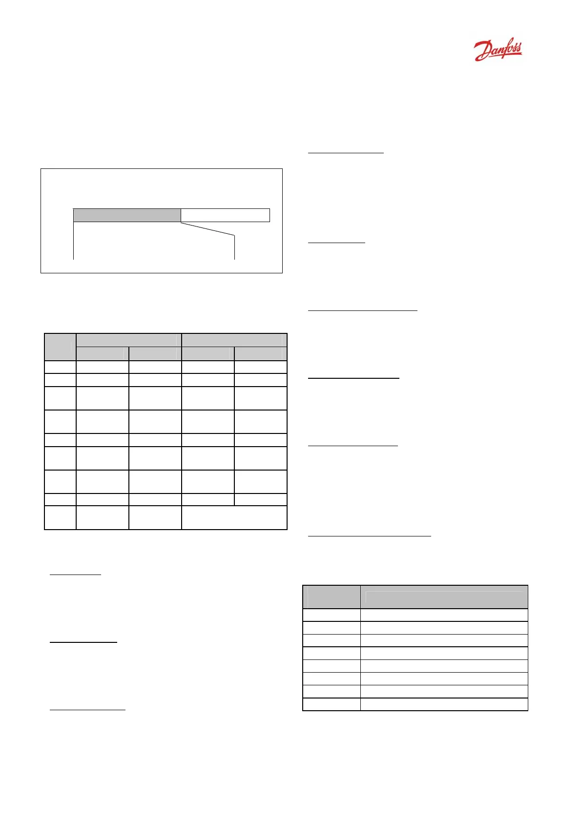
Slave → master
STW Actual RPM
Bit
no.:
15 14 13 12 11 10 9 8 7 6 5 4 3 2 1 0
Note that the bits 00 and 02 in Instance 70 are
identical with bits 00 and 02 in the more
extensive Instance 71.
Instance 70
Instance 71
Bit
Bit = 0 Bit =1 Bit = 0 Bit =1
00 - Fault
-
Fault
01 - -
-
Warning
02 -
Running
1 Fwd
- Running
1 Fwd
03 - -
- Running
2 Rev.
04 - -
-
Ready
05 - -
- Ctrl from
Net
06 - -
- Ref.
from Net
07 - - - At ref.
08-
15
- - State Attribute
Explanation of the Bits:
Bit 0, Fault
:
Bit 0 = "0" means that there is no fault in the
frequency converter.
Bit 0 = "1" means that there is a fault in the
frequency converter.
Bit 1, Warning
:
Bit 0 = "0" means that there is no unusual
situation.
Bit 0 = "1" means that an abnormal condition
has occurred.
Bit 2, Running 1
:
Bit 2 = "0" means that the drive is not in one
of these states or that Run 1 is not set.
Bit 2 = "1" means that the drive state attribute
is enabled or stopping, or that Fault-Stop and
bit 0 (Run 1) of the control word are set at the
same time.
Bit 3, Running 2
:
Bit 3 = "0" means that the drive is in neither of
these states or that Run 2 is not set.
Bit 3 = "1" means that the drive state attribute
is enabled or stopping, or that fault-stop and
bit 0 (Run 2) of the control word are set at the
same time.
Bit 4, Ready
:
Bit 4 = "0" means that the state attribute is in
another state.
Bit 4 = "1" means that the state attribute is
ready, enabled or stopping.
Bit 5, Control from net:
Bit 5 = "0" means that the drive is controlled
from the standard inputs.
Bit 5 = "1" means that EIP has control (start,
stop, reverse) of the drive.
Bit 6, Ref from net:
Bit 6 = "0" means that the reference comes
from inputs to the drive.
Bit 6 = "1" means that the reference comes
from EIP.
Bit 7, At reference:
Bit 7 = "0" means that the motor is running,
but that the present speed is different from the
preset speed reference, i.e. the speed is being
ramped up/down during start/stop.
Bit 7 = "1" means that the drive and reference
speeds are equal.
Bit 8 - 15, State attribute:
(Instance 71 only)
Represents the state attribute of the drive, as
indicated in the following table:
Bit
Number
Meaning
8 (Vendor specific)
9 Start up
10 Not ready
11 Ready
12 Enabled
13 Stopping
14 Fault stop
15 Faulted
For more detail of the actual output speed, see
the section Actual output speed under
Instances 20/70 and 21/71.

 Loading...


