VLT
®
AutomationDrive EtherNet/IP
- H o w t o C o n t r o l t h e F C 3 0 0 -
MG.90.Jx.02 ver. 5
th
September 2007 – VLT is a registered Danfoss trademark 28
ODVA Control Profile
Control Word under Instances 20/70 and
21/71
Set parameter 8-10 Control Word Profile to
ODVA, and select the instance in parameter
10-10 Process Data Type Selection.
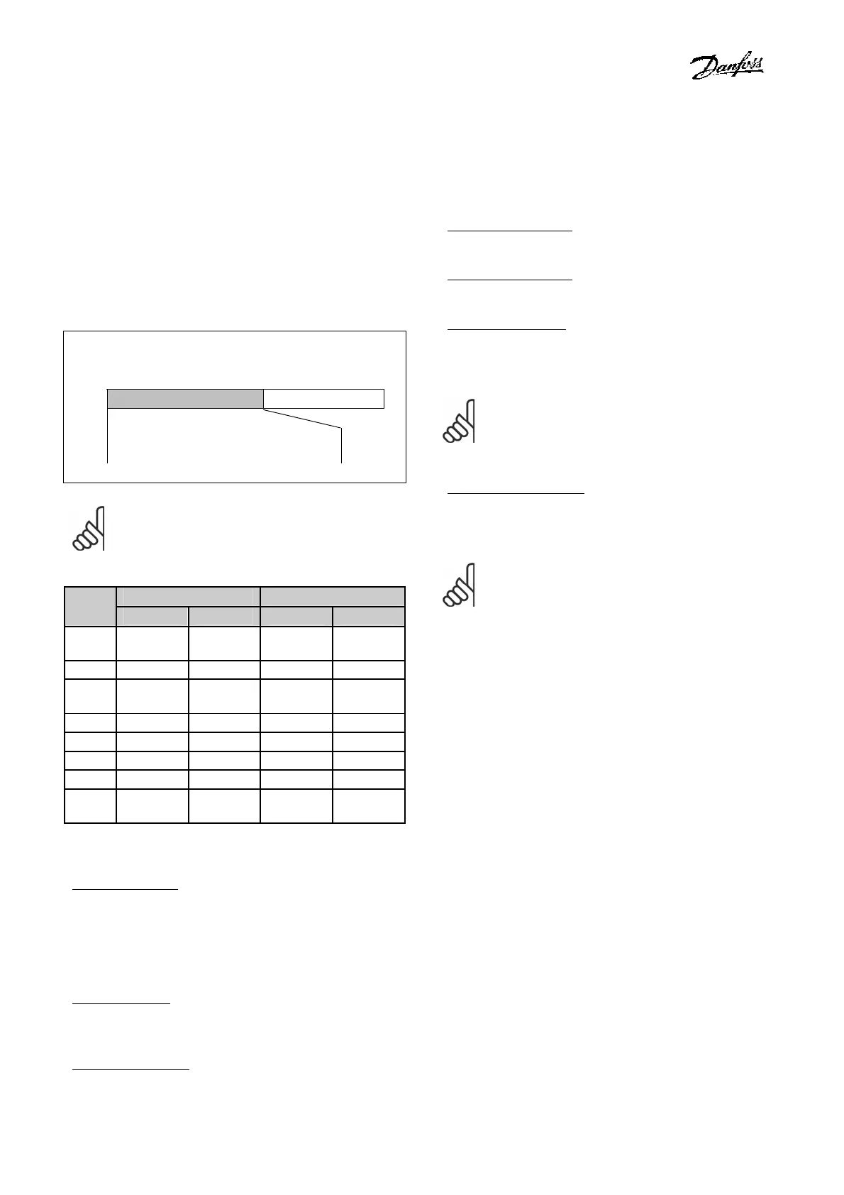
The control word in Instances 20 and 21 is
defined as follows:
Master → slave
CTW Speed ref. RPM
Bit
no.:
15 14 13 12 11 10 9 8 7 6 5 4 3 2 1 0
N.B.:
Note that the bits 00 and 02 in Instance
20 are identical with bits 00 and 02 in the
more extensive Instance 21.
Instance 20
Instance 21
Bit
Bit = 0 Bit =1 Bit = 0 Bit =1
00 Stop
Run
Fwd
Stop
Run
Fwd
01 - -
Stop Run Rev
02
No
function
Fault
reset
No
function
Fault
reset
03
- - - -
04
- - - -
05
- - - Net Ctrl
06
- - - Net Ref
07-
15
- - - -
Explanation of the Bits:
Bit 0, Run Fwd:
Bit 0 = "0" means that the VLT frequency
converter has a stop command.
Bit 0 = "1" leads to a start command and the
VLT frequency converter will start to run the
motor clockwise.
Bit 1, Run Rev
:
Bit 1 = "0" leads to a stop of the motor.
Bit 1 = "1" leads to a start of the motor.
Bit 2, Fault Reset
:
Bit 2 = "0" means that there is no reset of a
trip.
Bit 2 = "1" means that a trip is reset.
Bit 3, No function:
Bit 3 has no function.
Bit 4, No function:
Bit 4 has no function.
Bit 5, Net Control
:
Bit 5 = "0" means that the drive is controlled
from the standard inputs.
Bit 5 = "1" means that EIP controls the drive.
N.B.:
Please note that changes will affect
parameters 8-50 to 8-56.
Bit 6, Net Reference
:
Bit 6 = "0" Reference is from the standard
inputs.
Bit 6 = "1" Reference is from EIP.
N.B.:
Please note that changes will affect
parameters 3-15 to 3-17 Reference source
X.
For the Speed reference, see section Bus speed
reference value under Instances 20/70 and
21/71.

 Loading...


