VLT
®
AutomationDrive EtherNet/IP
MG.90.Jx.02 ver. 5
th
September 2007 – VLT is a registered Danfoss trademark 13
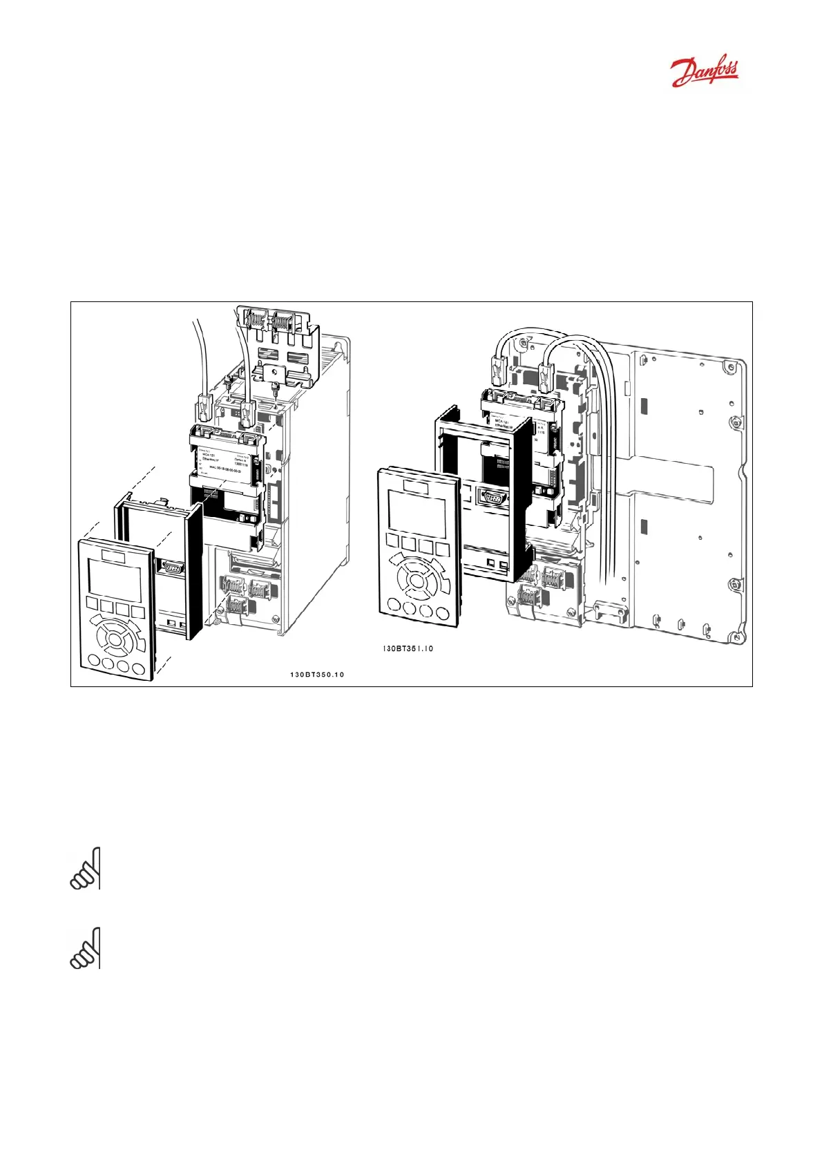
How to Install Option in Frequency Converter
Items required installing a fieldbus option in the frequency converter:
- The fieldbus option
- Fieldbus option adaptor frame for the FC 300. This frame is deeper than the standard frame, to
allow space for the fieldbus option beneath
- Strain relief (only for A1 and A2 enclosures)
Instructions:
- Remove LCP panel from the FC 300
- Remove the frame located beneath and discard
- Push the option into place. The Ethernet connectors must be facing upwards.
- Push the fieldbus option adaptor frame for the FC 300 into place
- Replace the LCP and attach cable
N.B.:
Don’t strip the Ethernet cable and ground via the strain relief-plate!
The grounding of screened Ethernet cable is done via the RJ-45 connector on the option.
N.B.:
After installing the MCA121 option, be aware of the following parameter settings:
Par. 8-01 Control Site [2] Controlword only or [0] Digital and ctrl. word
Par. 8-02 Control Word Source [3] Option A

 Loading...


