VLT
®
AutomationDrive EtherNet/IP
MG.90.Jx.02 ver. 5
th
September 2007 – VLT is a registered Danfoss trademark 9
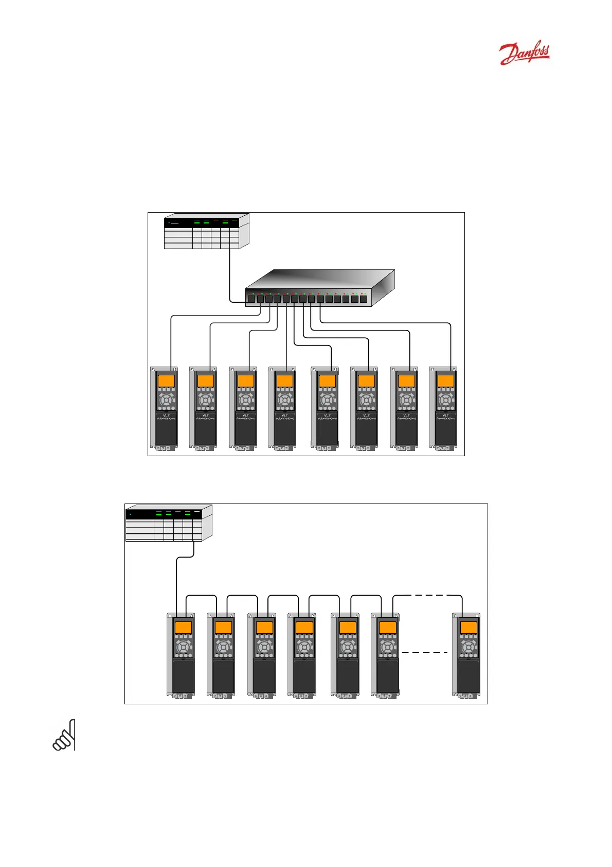
Topology
The MCA121 features a build-in Ethernet-switch, thus having two Ethernet RJ-45 connectors.
This enables the possibility for connecting several EtherNet/IP options in a line topology as an
alternative to the typical star-topology.
The two ports are equal, in the sense that they are transparent for the option. If only one connector is
used, either port can be used.
Star topology
Line topology
AutomationDrive
VLT
AutomationDrive
VLT
AutomationDrive
VLT
AutomationDrive
VLT
AutomationDrive
VLT
AutomationDrive
VLT
AutomationDrive
VLT
Note: For line topology please refer to section: “Recommended design rules”
In a line topology all drives must be powered, either by mains or 24 V DC option, for the build-
in switch to work.

 Loading...


