VLT
®
AutomationDrive EtherNet/IP
– H o w t o C o n t r o l t h e F C 3 0 0 –
MG.90.Jx.02 ver. 5
th
September 2007 – VLT is a registered Danfoss trademark 30
Reference Handling
Bus Speed Reference Value under Instances 100-101-103/150-151-153
In FC-Profile (par. 8-10 = [0] FC profile) the reference is scaled as a normalized relative value in
percent. The value is transmitted in hexadecimal:
0% = 0hex
100% = 4000hex
-100% = C000hex
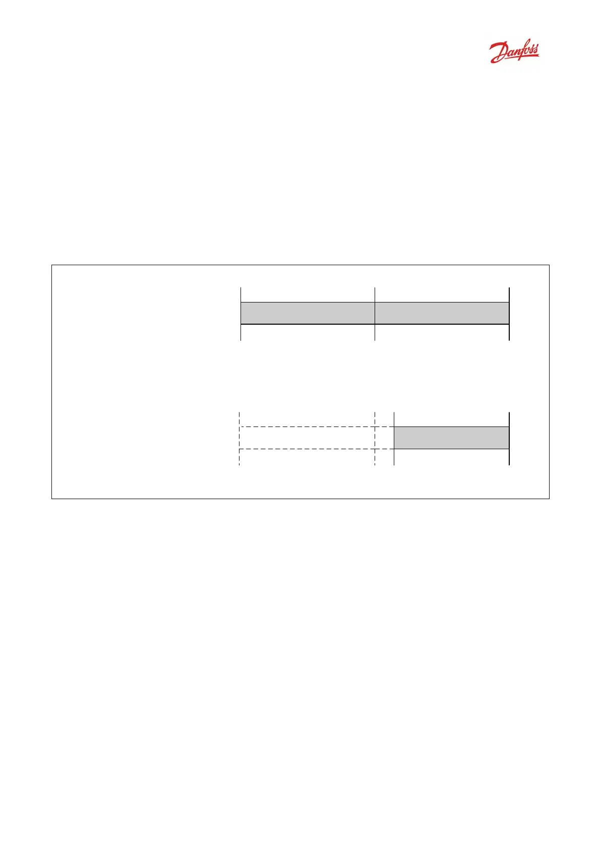
Depending of the setting of par. 3-00 Reference Range, the reference is scaled from – Max. to + Max.
or from Min. to Max.
-100%
(C000hex)
0%
(0hex)
100%
(4000hex)
0
par. 3-03
Max
reference
par. 3-03
Max
reference
0%
(0hex)
100%
(4000hex)
par. 3-03
Max
reference
par. 3-02
Min
reference
Forward
ForwardReverse
Par. 3-00 set to [1] -Max - +Max
Par. 3-00 set to [0] Min - Max
The actual reference [Ref. %] in the VLT depends on the settings in the following parameters:
Parameter 1-23 Motor frequency
Parameter 1-25 Motor nominal speed
Parameter 3-02 Minimum reference
Parameter 3-03 Maximum reference
All references provided to the frequency converter are added to the total reference value.
If a reference is to be controlled by the fieldbus only, ensure that all other reference inputs are zero.
This means that digital and analogue input terminals should not be used for reference signals.
The default setting (0%) should be maintained for preset references in par. 3-10 Preset Reference.
Note that if the bus speed reference is negative, and the control word contains a run reverse signal,
the drive will run clockwise
(- - is +).
MAV is scaled in the same way as the reference.

 Loading...


