3.13.3 16-5* Ref. & Feedb.
16-50 External Reference
Range: Function:
0 * [-200 - 200 ] View the total reference, the sum of digital,
analog,
preset, bus and freeze references, plus
catch-up and slow-down.
16-52 Feedback[Unit]
Range: Function:
0
ProcessCtrlUnit*
[-999999.999 -
999999.999
ProcessCtrlUnit]
View value of resulting
feedback
value after
processing of Feedback 1-3
(see 16-54 Feedback 1 [Unit],
16-55 Feedback 2 [Unit] and
16-56 Feedback 3 [Unit]) in
the feedback manager.
See parameter group 20-0*
Feedback.
The value is limited by
settings in and . Units as set
in 20-12 Reference/Feedback
Unit.
16-53 Digi Pot Reference
Range: Function:
0 * [-200 - 200 ] View the contribution of the Digital Potenti-
ometer
to the actual reference.
16-54 Feedback 1 [Unit]
Range: Function:
0
ProcessCtrlUnit*
[-999999.999 -
999999.999
ProcessCtrlUnit]
View value of Feedback 1,
see
parameter group 20-0*
Feedback.
The value is limited by
settings in 20-13 Minimum
Reference/Feedb. and
20-14 Maximum Reference/
Feedb.. Units as set in
20-12 Reference/Feedback
Unit.
16-55 Feedback 2 [Unit]
Range: Function:
0
ProcessCtrlUnit*
[-999999.999 -
999999.999
ProcessCtrlUnit]
View value of Feedback 2,
see parameter group 20-0*
Feedback.
The value is limited by
settings in 20-13 Minimum
Reference/Feedb. and
20-14 Maximum Reference/
Feedb.. Units as set in
20-12 Reference/Feedback
Unit.
16-56 Feedback 3 [Unit]
Range: Function:
0
ProcessCtrlUnit*
[-999999.999 -
999999.999
ProcessCtrlUnit]
View value of Feedback 3,
see
parameter group 20-0*
Feedback.
The value is limited by
settings in 20-13 Minimum
Reference/Feedb. and
20-14 Maximum Reference/
Feedb.. Units as set in
20-12 Reference/Feedback
Unit.
3.13.4 16-6* Inputs and Outputs
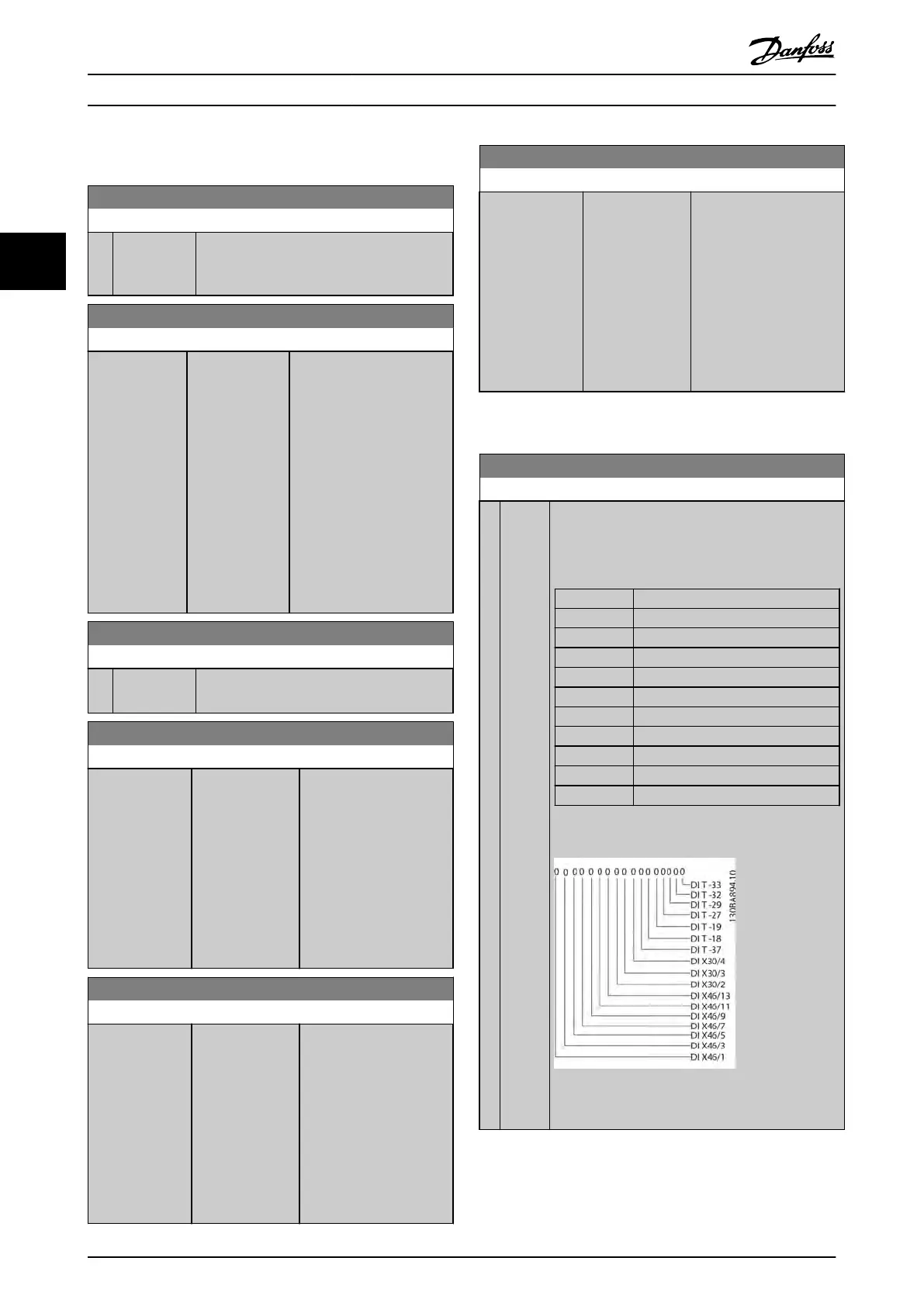
16-60 Digital Input
Range: Function:
0
*
[0 -
1023
]
View the signal states from the active digital inputs.
Example: Input 18 corresponds to bit no. 5, ‘0’ = no
signal, ‘1’ = connected signal. Bit 6 works in the
opposite way, on = '0', off = '1' (safe stop input).
Bit 0 Digital input term. 33
Bit 1 Digital input term. 32
Bit 2 Digital input term. 29
Bit 3 Digital input term. 27
Bit 4 Digital input term. 19
Bit 5 Digital input term. 18
Bit 6 Digital input term. 37
Bit 7 Digital input GP I/O term. X30/4
Bit 8 Digital input GP I/O term. X30/3
Bit 9 Digital input GP I/O term. X30/2
Bit 10-63 Reserved for future terminals
Table 3.20
Illustration 3.38
Parameter Description
VLT
®
Refrigeration Drive Programming Guide
106 MG16H102 - VLT
®
is a registered Danfoss trademark
33
 Loading...


