Illustration 3.50
NOTE
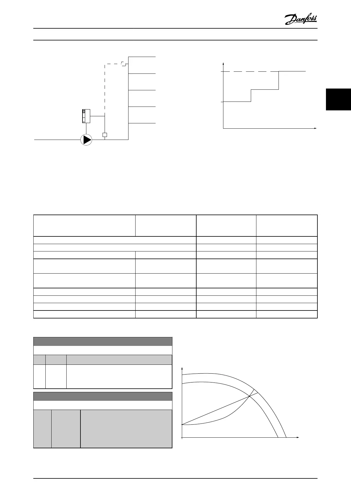
When
flow compensation is used with the Cascade
Controller (parameter group 25-**), the actual set-point will
not depend on speed (flow) but on the number of pumps
cut in. See below:
Set Point
P22-87
Number of pumps
H
(head)
H
DESIGN
H
MIN
130BA547.10
21 3
Illustration 3.51
There are two methods which can be employed,
depending upon whether or not the Speed at System
design Working Point is known.
Parameter used
Speed at
Design
Point
KNOWN
Speed at
Design
Point
UNKNOWN
Cascade Controller
22-80 Flow Compensation
+ + +
22-81 Square-linear Curve Approximation
+ + -
22-82 Work Point Calculation
+ + -
22-83 Speed at No-Flow [RPM]/22-84
Speed at No-
Flow [Hz]
+ + -
22-85 Speed at Design Point [RPM]/22-86
Speed at
Design Point [Hz]
+ - -
22-87 Pressure at No-Flow Speed
+ + +
22-88 Pressure at Rated Speed
- + -
22-89 Flow at Design Point
- + -
22-90 Flow at Rated Speed
- + -
Table 3.26
22-80 Flow Compensation
Option: Function:
[0] * Disabled Set-Point compensation not active.
[1] Enabled Set-Point compensation is active. Enabling this
parameter
allows the Flow Compensated Setpoint
operation.
22-81 Square-linear Curve Approximation
Range: Function:
100 %* [0 - 100 %] Example 1:
Adjustment
of this parameter allows the
shape of the control curve to be adjusted.
0 = Linear
100% = Ideal shape (theoretical).
NOTE
Not
visible when running in cascade.
Control Curve
(head)
(ow)
H
Q
130BA388.11
100%
P22-81 0%
Illustration 3.52
Parameter Description
VLT
®
Refrigeration Drive Programming Guide
MG16H102 - VLT
®
is a registered Danfoss trademark
137
3 3
 Loading...


