22-82 Work Point Calculation
Option: Function:
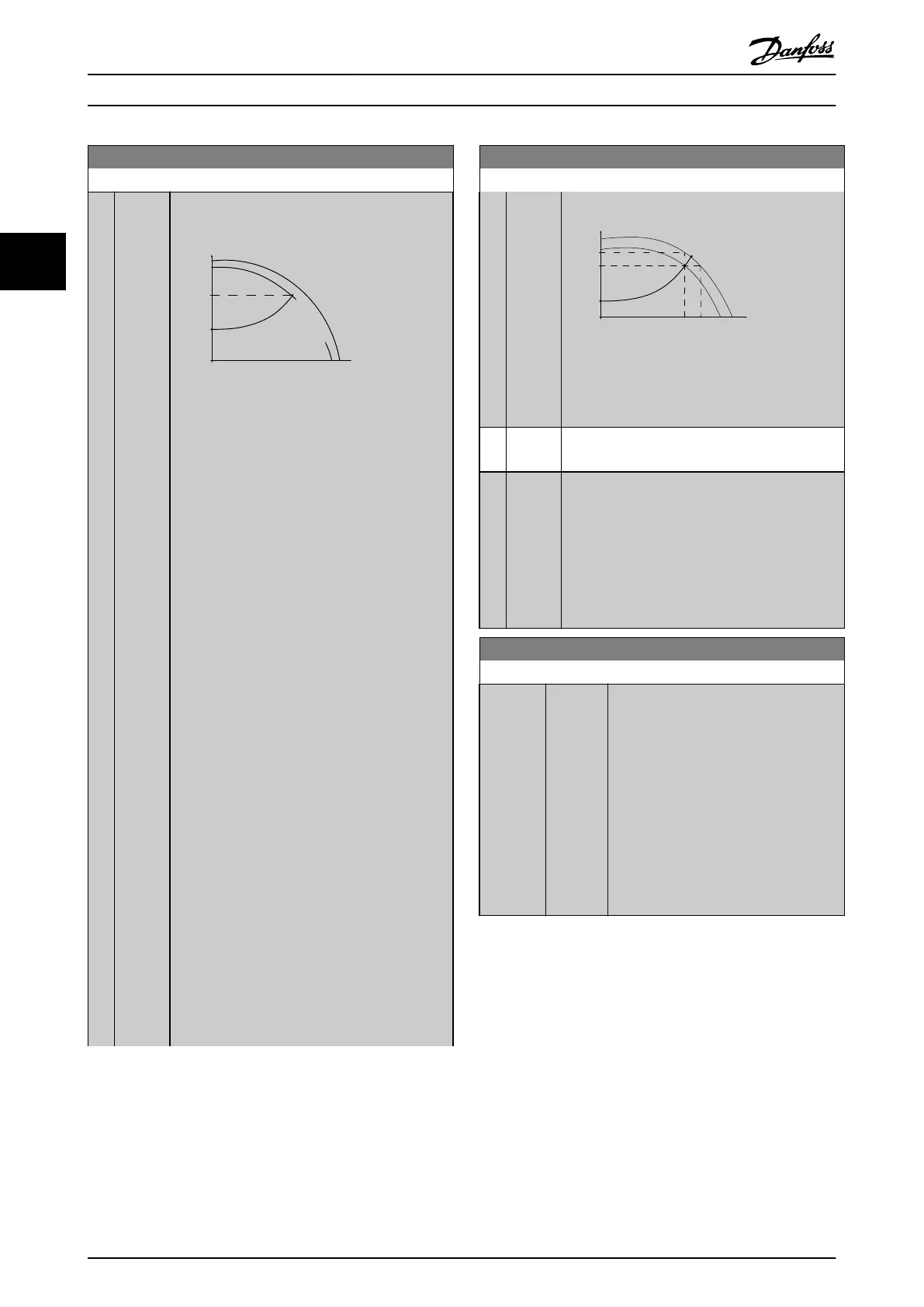
Example 1:
A
130BA385.11
P22-85/22-86
Control Curve
H
MIN
H
DESIGN
Set Point
n
RATED
_
f
RATED
n
DESIGN
-
f
DESIGN
Q
(flow)
H
(head)
Par.:
22-83/
22-84/
22-87
Illustration 3.53 Speed at System Design Working
Point
is Known
From the data sheet showing characteristics for
the
specific equipment at different speeds, simply
reading across from the H
DESIGN
point and the
Q
DESIGN
point allows us to find point A, which is
the System Design Working Point. The pump
characteristics at this point should be identified
and the associated speed programmed. Closing
the valves and adjusting the speed until H
MIN
has
been achieved allows the speed at the no flow
point to be identified.
Adjustment of 22-81 Square-linear Curve Approxi-
mation then allows the shape of the control curve
to be adjusted infinitely.
Example 2:
Speed at System Design Working Point is not
known: Where the Speed at System Design
Working Point is unknown, another reference
point on the control curve needs to be
determined by means of the data sheet. By
looking at the curve for the rated speed and
plotting the design pressure (H
DESIGN
, Point C) the
flow at that pressure Q
RATED
can be determined.
Similarly, by plotting the design flow (Q
DESIGN
,
Point D). The pressure H
DESIGN
at that flow can be
determined. Knowing these two points on the
pump curve, along with H
MIN
as described above,
allows the frequency converter to calculate the
reference point B and thus to plot the control
curve which will also include the System design
Working Point A.
22-82 Work Point Calculation
Option: Function:
Set point
Control Curve
n
D
E
S
I
G
N
-
f
D
E
S
I
G
N
n
R
A
T
E
D
-
f
R
A
T
E
D
(head)H
H
RATED
Par.
22-88
Q
DESIGN
Par.
22-89
H
MIN
D
B
C
A
Q
RATED
Par.
22-90
(flow)
Q
H
DESIGN
130BA387.11
22-84/
22-87
22-83/
Par.:
Illustration 3.54
[0]
*
Disabled Work Point Calculation not active. To be used if
speed
at design point is known (see Table 3.26).
[1] Enabled Work Point Calculation is active. Enabling this
parameter
allows the calculation of the unknown
System Design Working Point at 50/60 Hz speed,
from the input data set in 22-83 Speed at No-Flow
[RPM] 22-84 Speed at No-Flow [Hz], 22-87 Pressure
at No-Flow Speed, 22-88 Pressure at Rated Speed,
22-89 Flow at Design Point and 22-90 Flow at Rated
Speed.
22-83 Speed at No-Flow [RPM]
Range: Function:
Size
related*
[ 0
- par.
22-85
RPM]
Resolution
1 RPM.
The speed of the motor at which flow Is
zero and minimum pressure H
MIN
is
achieved should be entered here in RPM.
Alternatively, the speed in Hz can be
entered in 22-84 Speed at No-Flow [Hz]. If
it has been decided to use RPM in
0-02 Motor Speed Unit then 22-85 Speed at
Design Point [RPM] should also be used.
Closing the valves and reducing the
speed until minimum pressure H
MIN
is
achieved will determine this value.
Parameter Description
VLT
®
Refrigeration Drive Programming Guide
138 MG16H102 - VLT
®
is a registered Danfoss trademark
33
 Loading...


