For example ETR-3 starts calculating when set-up 3 is
selected.
For the North American market: The ETR
functions provide class 20 motor overload protection in
accordance with NEC.
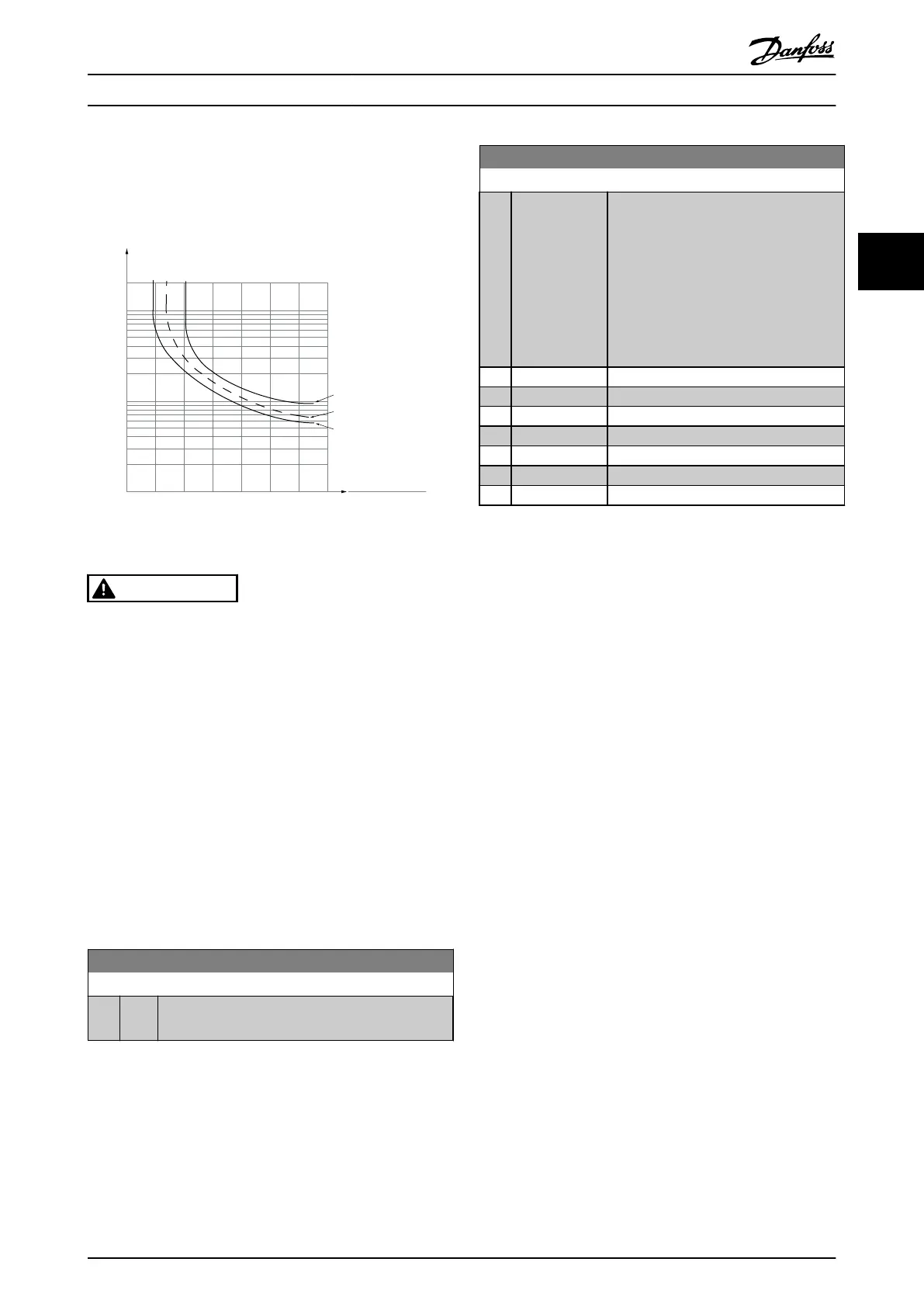
1.21.0 1.4
30
10
20
100
60
40
50
1.81.6 2.0
2000
500
200
400
300
1000
600
t [s]
175ZA052.12
f
OUT
= 2 x f
M,N
f
OUT
= 0.2 x f
M,N
f
OUT
= 1 x f
M,N
(par. 1-23)
I
MN
(par. 1-24)
I
M
Illustration 3.10
WARNING
In order to maintain PELV, all connections made to the
control
terminals must be PELV, e.g. thermistor must be
reinforced/double insulated
NOTE
Danfoss
recommends using 24 V DC as thermistor supply
voltage.
NOTE
The
ETR timer function does not work when 1-10 Motor
Construction = [1] PM, non salient SPM.
NOTE
For
correct operation of ETR function setting in 1-03 Torque
Characteristics must fit the application (see description of
1-03 Torque Characteristics).
1-91 Motor External Fan
Option: Function:
[0] * None No external fan is required, i.e. the motor is derated
at
low speed.
1-93 Thermistor Source
Option: Function:
Select the input to which the thermistor
(PTC
sensor) should be connected. An
analog input option [1] or [2] cannot be
selected if the analog input is already in
use as a reference source (selected in
3-15 Reference 1 Source, 3-16 Reference 2
Source or 3-17 Reference 3 Source).
When using MCB 112, choice [0] None
must always be selected.
[0] * None
[1] Analog Input 53
[2] Analog Input 54
[3] Digital input 18
[4] Digital input 19
[5] Digital input 32
[6] Digital input 33
NOTE
This
parameter cannot be adjusted while the motor is
running.
NOTE
Digital
input should be set to [0] PNP - Active at 24 V in
5-00 Digital I/O Mode.
Parameter Description
VLT
®
Refrigeration Drive Programming Guide
MG16H102 - VLT
®
is a registered Danfoss trademark
47
3 3

 Loading...


