3-13 Reference Site
Option: Function:
Select which reference site to activate.
[0] * Linked to
Hand
/ Auto
Use local reference when in Hand mode; or
remote reference when in Auto mode.
[1] Remote Use remote reference in both Hand mode
and
Auto mode.
[2] Local Use local reference in both Hand mode and
Auto
mode.
NOTE
When set to [2] Local, the frequency
converter will start with this setting
again following a 'power down'.
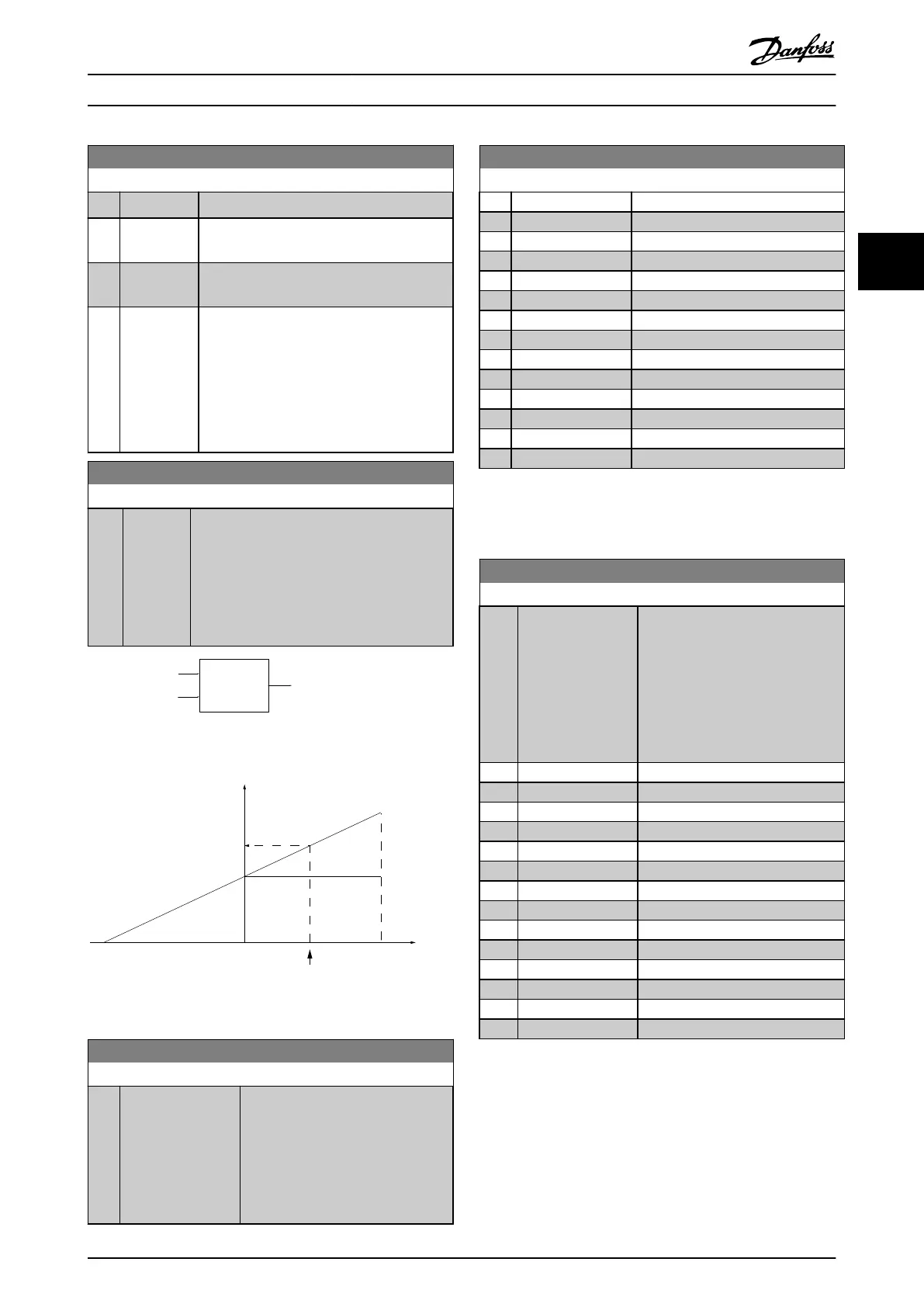
3-14 Preset Relative Reference
Range: Function:
0 %* [-100 -
100
%]
The actual reference, X, is increased or
decreased with the percentage Y, set in
3-14 Preset Relative Reference. This results in the
actual reference Z. Actual reference (X) is the
sum of the inputs selected in 3-15 Reference 1
Source, 3-16 Reference 2 Source, 3-17 Reference
3 Source and 8-02 Control Source.
Relative
Z=X+X*Y/100
Resulting
actual
reference
Y
X
130BA059.12
Z
Illustration 3.13
X
100
%
0-100
Z
Y
X+X*Y/100
P 3-14
130BA278.10
Illustration 3.14
3-15 Reference 1 Source
Option: Function:
Select the reference input to be used
for
the first reference signal.
3-15 Reference 1 Source, 3-16 Reference
2 Source and 3-17 Reference 3 Source
define up to three different reference
signals. The sum of these reference
signals defines the actual reference.
3-15 Reference 1 Source
Option: Function:
[0] No function
[1] * Analog Input 53
[2] Analog Input 54
[7] Pulse input 29
[8] Pulse input 33
[20] Digital pot.meter
[21] Analog input X30/11
[22] Analog input X30/12
[23] Analog Input X42/1
[24] Analog Input X42/3
[25] Analog Input X42/5
[30] Ext. Closed Loop 1
[31] Ext. Closed Loop 2
[32] Ext. Closed Loop 3
NOTE
This
parameter cannot be changed while the motor is
running.
3-16 Reference 2 Source
Option: Function:
Select the reference input to be
used
for the second reference
signal. 3-15 Reference 1 Source,
3-16 Reference 2 Source and
3-17 Reference 3 Source define up to
three different reference signals. The
sum of these reference signals
defines the actual reference.
[0] No function
[1] Analog Input 53
[2] Analog Input 54
[7] Pulse input 29
[8] Pulse input 33
[20] * Digital pot.meter
[21] Analog input X30/11
[22] Analog input X30/12
[23] Analog Input X42/1
[24] Analog Input X42/3
[25] Analog Input X42/5
[30] Ext. Closed Loop 1
[31] Ext. Closed Loop 2
[32] Ext. Closed Loop 3
NOTE
This
parameter cannot be changed while the motor is
running.
Parameter Description
VLT
®
Refrigeration Drive Programming Guide
MG16H102 - VLT
®
is a registered Danfoss trademark
51
3 3
 Loading...


