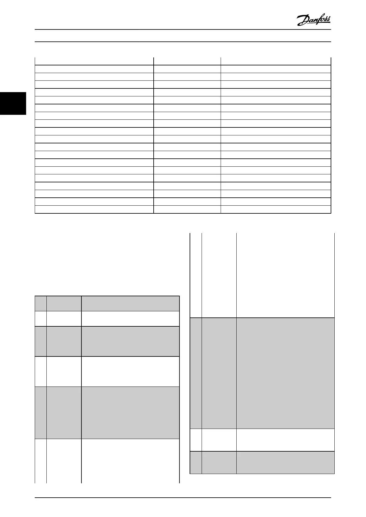
Fire mode [37]
Day/ Night Control [39]
Run Permissive [52]
Hand start [53]
Auto start [54]
DigiPot Increase [55] All
DigiPot Decrease [56] All
DigiPot Clear [57] All
Reset Counter A [62] All
Reset Counter B [65] All
Sleep Mode [66]
Reset Maintenance Word [78]
Lead Compressor Start [120]
Lead Compressor Alternation [121]
Compressor 1 Interlock [130]
Compressor 2 Interlock [131]
Compressor 3 Interlock [132]
Comp. 1 Inv. Interlock [139]
Comp. 2 Inv. Interlock [140]
Comp. 3 Inv. Interlock [141]
Table 3.9
All = Terminals 18, 19, 27, 29, 32, X30/2, X30/3, X30/4. X30/
are the terminals on MCB 101.
Functions dedicated to only one digital input are stated in
the associated parameter.
All digital inputs can be programmed to these functions:
[0] No operation No reaction to signals transmitted to
terminal.
[1] Reset Resets frequency converter after a TRIP/
ALARM.
Not all alarms can be reset.
[2] Coast inverse
Leaves motor in free mode. Logic ‘0’ ⇒
coasting stop.
(Default Digital input 27): Coasting stop,
inverted input (NC).
[3] Coast and
reset
inverse
Reset and coasting stop Inverted input (NC).
Leaves motor in free mode and resets the
frequency converter. Logic ‘0’ ⇒ coasting
stop and reset.
[5] DC-brake
inverse
Inverted input for DC braking (NC).
Stops
motor by energizing it with a DC
current for a certain time period. See
2-01 DC Brake Current to 2-03 DC Brake Cut
In Speed [RPM]. The function is only active
when the value in 2-02 DC Braking Time is
different from 0. Logic ’0’ ⇒ DC braking.
[6] Stop inverse Stop Inverted function. Generates a stop
function when the selected terminal goes
from logical level ‘1’ to ‘0’. The stop is
performed according to the selected ramp
time (3-42 Ramp 1 Ramp Down Time,
3-52 Ramp 2 Ramp Down Time, 3-62 Ramp 3
Ramp down Time, 3-72 Ramp 4 Ramp Down
Time).
NOTE
When the frequency converter is at the
torque limit and has received a stop
command, it may not stop by itself. To
ensure that the frequency converter
stops, configure a digital output to [27]
Torque limit & stop and connect this
digital output to a digital input that is
configured as coast.
[7] External
Interlock
Same function as Coasting stop, inverse, but
External Interlock generates the alarm
message ’external fault’ on the display
when the terminal which is programmed for
Coast Inverse is logic ‘0’. The alarm message
will also be active via digital outputs and
relay outputs, if programmed for External
Interlock. The alarm can be reset using a
digital input or the [Reset] key if the cause
for the External Interlock has been
removed. A delay can be programmed in
22-00 External Interlock Delay. After applying
a signal to the input, the reaction described
above will be delayed with the time set in
22-00 External Interlock Delay.
[8] Start Select start for a start/stop command. Logic
‘1’
= start, logic ‘0’ = stop.
(Default Digital input 18)
[9] Latched start Motor starts, if a pulse is applied for min. 2
ms.
Motor stops when Stop inverse is
activated
Parameter Description
VLT
®
Refrigeration Drive Programming Guide
60 MG16H102 - VLT
®
is a registered Danfoss trademark
33
 Loading...


