3.5.4 3-5* Ramp 2
Choosing ramp parameters, see parameter group 3-4*.
3-51 Ramp 2 Ramp Up Time
Range: Function:
Size
related*
[ 1.00
-
3600
s]
Enter the ramp-up time, i.e. the acceleration
time from 0 RPM to 1-25 Motor Nominal Speed.
Choose a ramp-up time such that the output
current does not exceed the current limit in
4-18 Current Limit during ramping. See ramp-
down time in 3-52 Ramp 2 Ramp Down Time.
par
. 3 − 51 =
tacc
×
nnom
par
. 1 − 25
ref
rpm
s
3-52 Ramp 2 Ramp Down Time
Range: Function:
Size
related*
[ 1.00
-
3600
s]
Enter the ramp-down time, i.e. the deceleration
time from 1-25 Motor Nominal Speed to 0 RPM.
Choose a ramp-down time such that no over-
voltage arises in the inverter due to
regenerative operation of the motor, and such
that the generated current does not exceed
the current limit set in 4-18 Current Limit. See
ramp-up time in 3-51 Ramp 2 Ramp Up Time.
par
.3 − 52 =
tdec
×
nnom
par
. 1 − 25
ref
rpm
s
3.5.5 3-8* Other Ramps
Configure parameters for special ramps e.g. Jog.
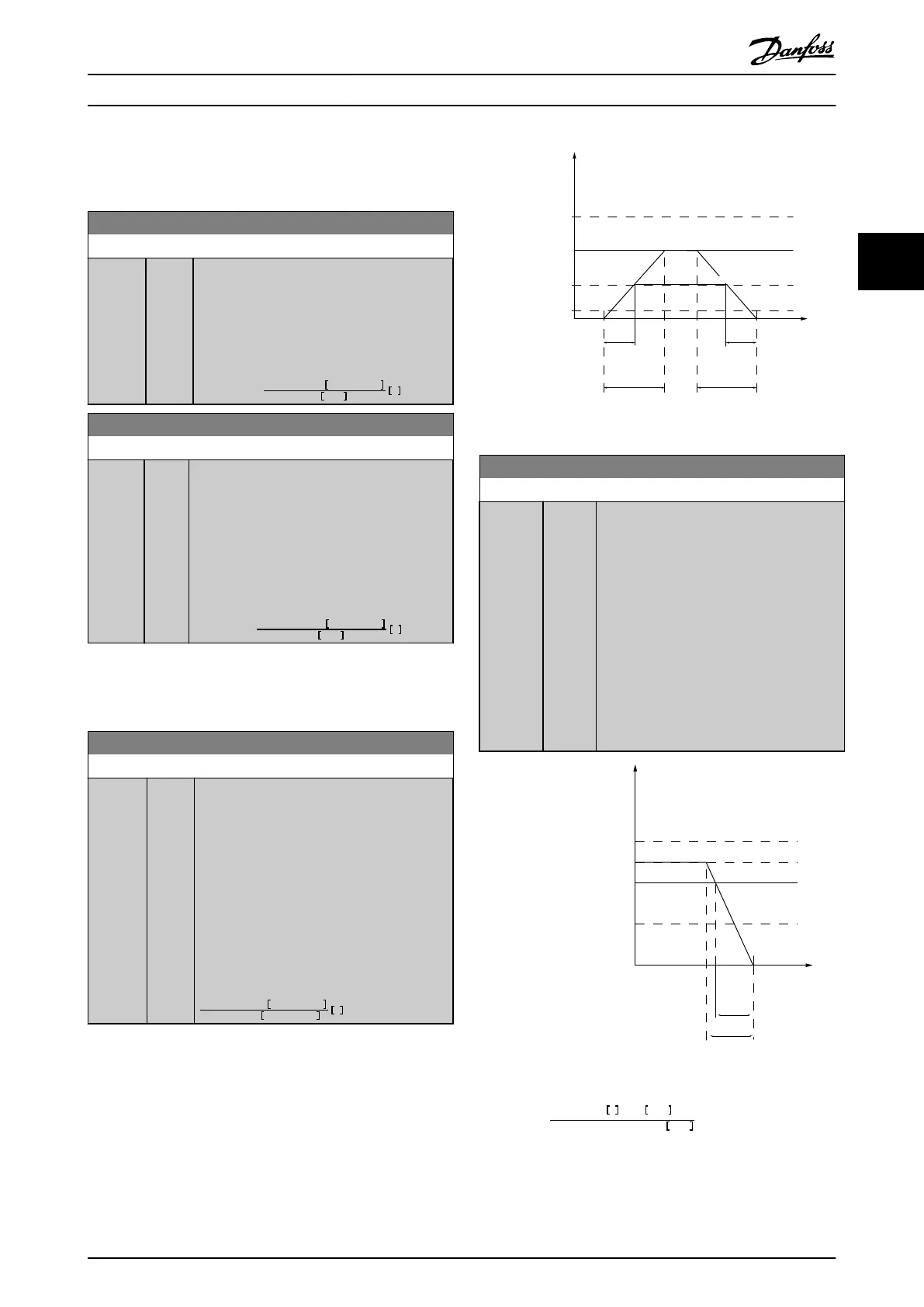
3-80 Jog Ramp Time
Range: Function:
Size
related*
[1 -
3600
s]
Enter the jog ramp time, i.e. the acceleration/
deceleration time between 0 RPM and the
rated motor speed (n
M,N
) (set in 1-25 Motor
Nominal Speed). Ensure that the resultant
output current required for the given jog
ramp time does not exceed the current limit
in 4-18 Current Limit. The jog ramp time starts
upon activation of a jog signal via the control
panel, a selected digital input, or the serial
communication port.
par
. 3 − 80 =
tjog
×
nnom
par
. 1 − 25
jog
speed
par
. 3 − 19
s
130BA070.10
Time
P 3-80
RPM
P 4-13 RPM
high limit
P 1-25
Motor speed
Jog speed
P 3-19
P 3-80
Ramp up
(acc)
Ramp down
(dec)
t jog t jog
P 4-11 RPM
low limit
Illustration 3.16
3-81 Quick Stop Ramp Time
Range: Function:
Size
related*
[1 -
3600
s]
Enter the quick–stop ramp-down time, i.e.
the deceleration time from the synchronous
motor speed to 0 RPM. Ensure that no
resultant over-voltage will arise in the
inverter due to regenerative operation of
the motor required to achieve the given
ramp-down time. Ensure also that the
generated current required to achieve the
given ramp-down time does not exceed the
current limit (set in 4-18 Current Limit).
Quick-stop is activated by means of a signal
on a selected digital input, or via the serial
communication port.
130BA069.10
Time
RPM
P 4-13 RPM
high limit
Reference
P 1-25
Motor speed
low limit
P 4-11 RPM
P 3-81
Qramp
Qstop
Illustration 3.17
Par
. 3 − 81 =
t
Qstop
s
x
n
s
RPM
Δ
jog
ref
(
par
. 3 − 19
)
RPM
Parameter Description
VLT
®
Refrigeration Drive Programming Guide
MG16H102 - VLT
®
is a registered Danfoss trademark
53
3 3
 Loading...


