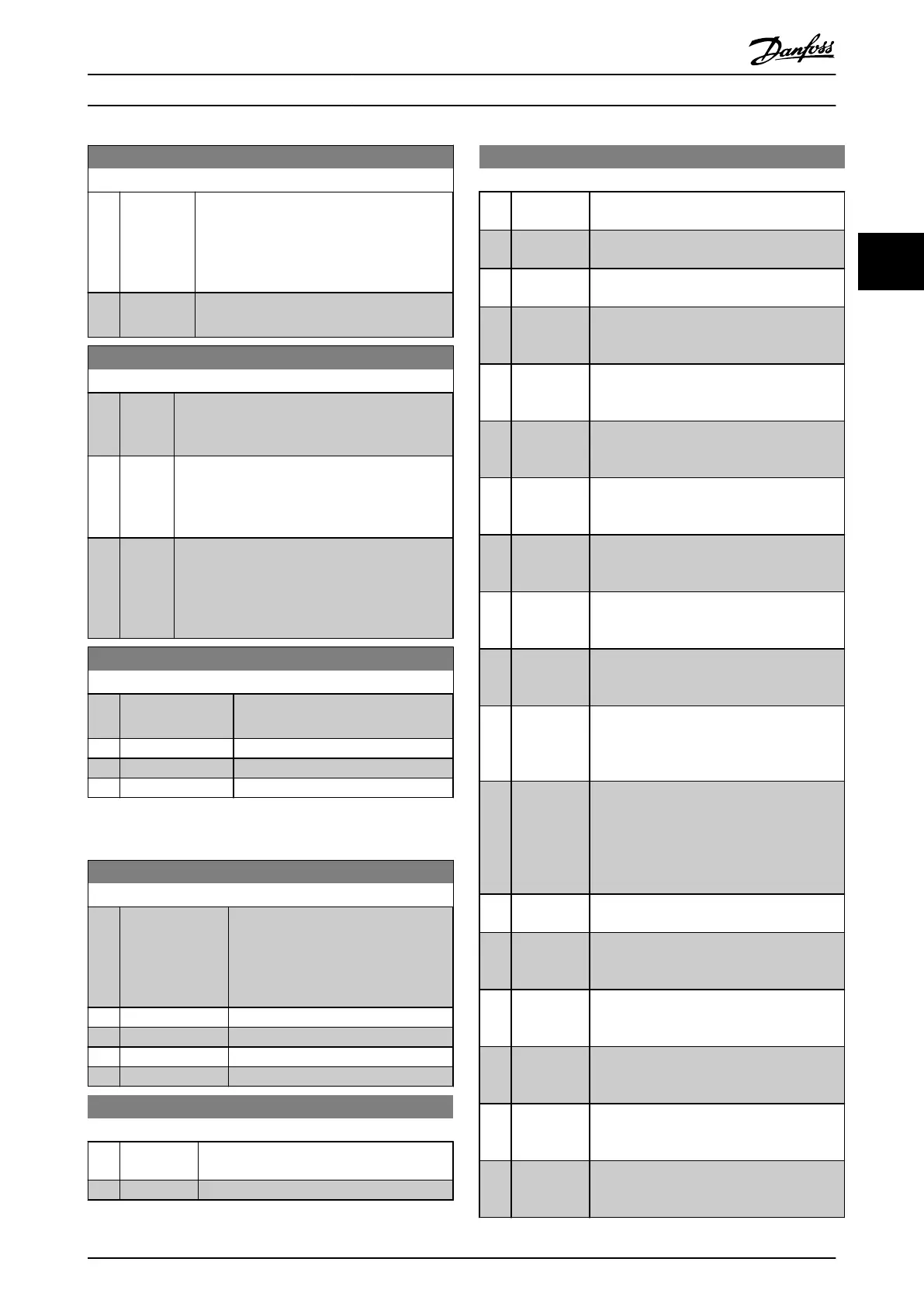
8-05 End-of-Timeout Function
Option: Function:
[0] Hold set-up
Retains the set-up selected in 8-04
Control
Timeout Function and displays a warning, until
8-06 Reset Control Timeout toggles. Then the
frequency converter resumes its original set-
up.
[1] * Resume set-
up
Resumes the set-up active before the time-
out.
8-06 Reset Control Timeout
Option: Function:
This parameter is active only when the choice [0]
Hold
set-up has been selected in 8-05 End-of-
Timeout Function.
[0] * Do not
reset
Retains the set-up specified in 8-04
Control
Timeout Function, [7] Set-up 1, [8] Set-up 2, [9] Set-
up 3 and [10] Set-up 4 following a control time-
out.
[1] Do
reset
Returns the frequency converter to the original
set-up
following a control word time-out. When
the value is set to [1] Do reset, the frequency
converter performs the reset and then
immediately reverts to the [0] Do not reset setting.
8-07 Diagnosis Trigger
Option: Function:
This parameter has no function for
BACnet.
[0] * Disable
[1] Trigger on alarms
[2] Trigger alarm/warn.
3.9.3 8-1* Ctrl. Word Settings
8-10 Control Profile
Option: Function:
Select the interpretation of the control
and
status words corresponding to the
installed fieldbus. Only the selections
valid for the fieldbus installed in slot A
will be visible in the LPC display.
[0] * FC profile
[1] PROFIdrive profile
[5] ODVA
[7] CANopen DSP 402
8-13 Configurable Status Word STW
Option: Function:
This parameter enables configuration of bits
12–15
in the status word.
[0] No function
8-13 Configurable Status Word STW
Option: Function:
[1] * Profile
Default
Function corresponds to the profile default
selected
in 8-10 Control Profile.
[2] Alarm 68
Only
Only set in case of an Alarm 68.
[3] Trip excl.
Alarm
68
Set in case of a trip, except if Alarm 68
executes the trip.
[10] T18 DI
status.
The bit indicates the status of terminal 18.
“0”
indicates that the terminal is low
“1” indicates that the terminal is high
[11] T19 DI
status.
The bit indicates the status of terminal 19.
“0”
indicates that the terminal is low
“1” indicates that the terminal is high
[12] T27 DI
status.
The bit indicates the status of terminal 27.
“0”
indicates that the terminal is low
“1” indicates that the terminal is high
[13] T29 DI
status.
The bit indicates the status of terminal 29.
“0”
indicates that the terminal is low
“1” indicates that the terminal is high
[14] T32 DI
status.
The bit indicates the status of terminal 32.
“0”
indicates that the terminal is low
“1” indicates that the terminal is high
[15] T33 DI
status.
The bit indicates the status of terminal 33.
“0”
indicates that the terminal is low
“1” indicates that the terminal is high
[16] T37 DI
status
The bit indicates the status of terminal 37.
0”
indicates T37 is low (safe stop)
“1” indicates T37 is high (normal)
[21] Thermal
warning
The thermal warning turns on when the
temperature
exceeds the limit in the motor,
the frequency converter, the brake resistor,
or the thermistor.
[30] Brake fault
(IGBT)
Output is Logic ‘1’ when the brake IGBT is
short-circuited.
Use this function to protect
the frequency converter if there is a fault on
the brake modules. Use the output/relay to
cut out the main voltage from the frequency
converter.
[40] Out of ref.
range
[60] Comtor 0 See parameter group 13-1*. If Comtor 0 is
evaluated
as TRUE, the output goes high.
Otherwise, it is low.
[61] Comtor 1 See parameter group 13-1*. If Comtor 1 is
evaluated
as TRUE, the output goes high.
Otherwise, it is low.
[62] Comtor 2 See parameter group 13-1*. If Comtor 2 is
evaluated
as TRUE, the output goes high.
Otherwise, it is low.
[63] Comtor 3 See parameter group 13-1*. If Comtor 3 is
evaluated
as TRUE, the output goes high.
Otherwise, it is low.
[64] Comtor 4 See parameter group 13-1*. If Comtor 4 is
evaluated
as TRUE, the output goes high.
Otherwise, it is low.
Parameter Description
VLT
®
Refrigeration Drive Programming Guide
MG16H102 - VLT
®
is a registered Danfoss trademark
79
3 3
 Loading...


