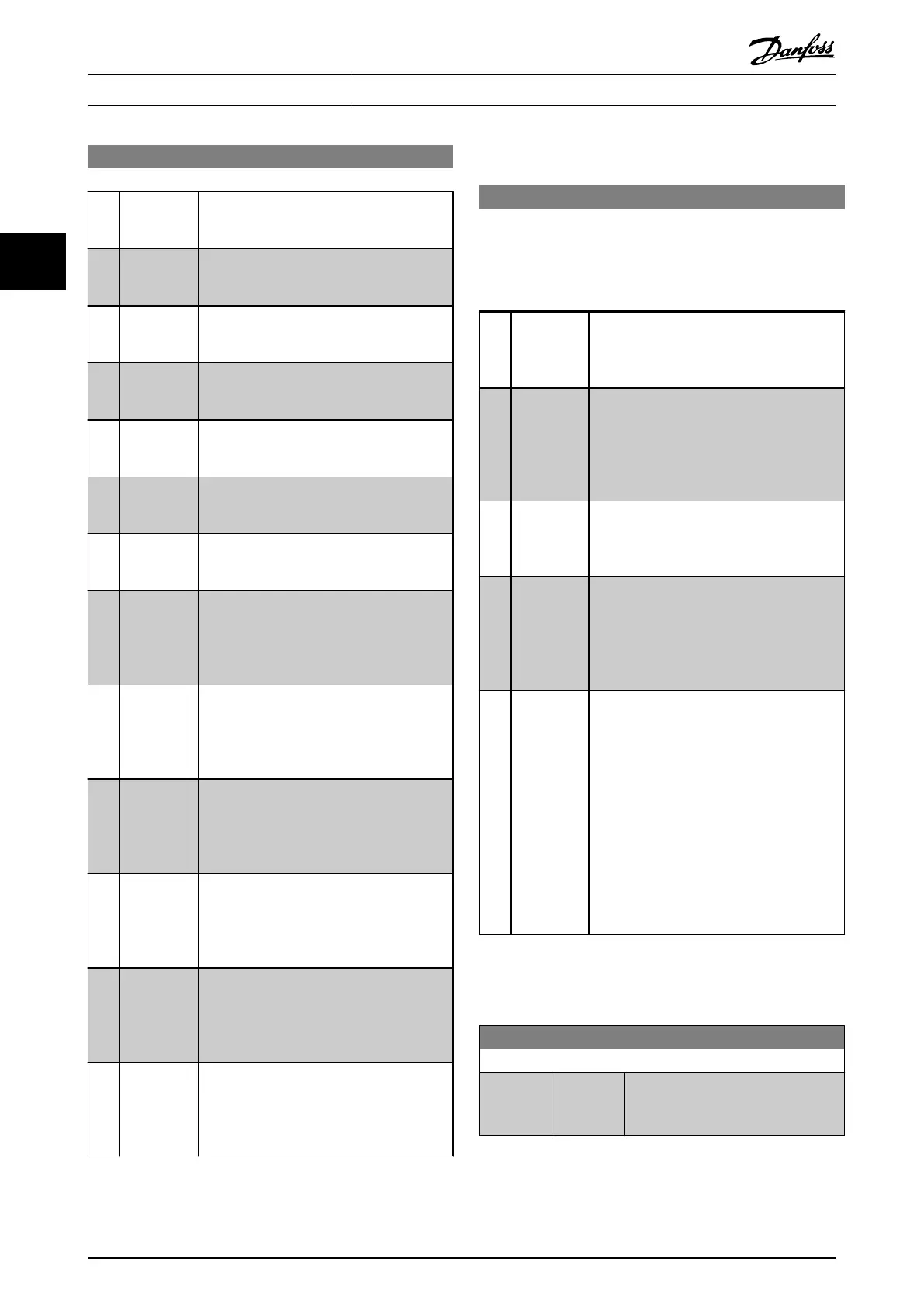
8-13 Configurable Status Word STW
Option: Function:
[65] Comtor 5 See parameter group 13-1*. If Comtor 5 is
evaluated
as TRUE, the output goes high.
Otherwise, it is low.
[70] Logic Rule 0 See parameter group 13-4*. If Logic Rule 0 is
evaluated
as TRUE, the output goes high.
Otherwise, it is low.
[71] Logic Rule 1 See parameter group 13-4*. If Logic Rule 1 is
evaluated
as TRUE, the output goes high.
Otherwise, it is low.
[72] Logic Rule 2 See parameter group 13-4*. If Logic Rule 2 is
evaluated
as TRUE, the output goes high.
Otherwise, it is low.
[73] Logic Rule 3 See parameter group 13-4*. If Logic Rule 3 is
evaluated
as TRUE, the output goes high.
Otherwise, it is low.
[74] Logic Rule 4 See parameter group 13-4*. If Logic Rule 4 is
evaluated
as TRUE, the output goes high.
Otherwise, it is low.
[75] Logic Rule 5 See parameter group 13-4*. If Logic Rule 5 is
evaluated
as TRUE, the output goes high.
Otherwise, it is low.
[80] SL Digital
Output
A
See 13-52 SL Controller Action. The output
goes high whenever the Smart Logic Action
[38] Set digital out A high is executed. The
output goes low whenever the Smart Logic
Action [32] Set digital out A low is executed.
[81] SL Digital
Output
B
See 13-52 SL Controller Action. The input goes
high whenever the Smart Logic Action [39]
Set digital out B high is executed. The input
goes low whenever the Smart Logic Action
[33] Set digital out B low is executed.
[82] SL Digital
Output
C
See 13-52 SL Controller Action. The input goes
high whenever the Smart Logic Action [40]
Set digital out C high is executed. The input
goes low whenever the Smart Logic Action
[34] Set digital out C low is executed.
[83] SL Digital
Output
D
See 13-52 SL Controller Action. The input goes
high whenever the Smart Logic Action [41]
Set digital out D high is executed. The input
goes low whenever the Smart Logic Action
[35] Set digital out D low is executed.
[84] SL Digital
Output
E
See 13-52 SL Controller Action. The input goes
high whenever the Smart Logic Action [42]
Set digital out E high is executed. The input
goes low whenever the Smart Logic Action
[36] Set digital out E low is executed.
[85] SL Digital
Output
F
See 13-52 SL Controller Action. The input goes
high whenever the Smart Logic Action [43]
Set digital out F high is executed. The input
goes low whenever the Smart Logic Action
[37] Set digital out F low is executed.
3.9.4 8-3* FC Port Settings
8-30 Protocol
Protocol selection for the integrated FC (standard) Port (RS-485)
on
the control card.
Parameter group 8-7* is only visible when FC Option [9] is
chosen.
Option: Function:
[0] * FC Communication according to the FC Protocol
as
described in the VLT Refrigeration Drive FC
103 Design Guide, chapter: RS-485 Installation
and Set-up.
[1] FC MC
Same as FC [0]
but to be used when
downloading SW to the frequency converter
or uploading dll file (covering information
regarding parameters available in the
frequency converter and their inter-depend-
encies) to Motion Control Tool MCT10.
[2] Modbus
RTU
Communication according to the Modbus
RTU
protocol as described in the VLT Refrig-
eration Drive FC 103 Design Guide, chapter:
RS-485 Installation and Set-up.
[3] Metasys N2 Communication protocol. The N2 software
protocol
is designed to be general in nature
in order to accommodate the unique
properties each device may have. Please see
sete manual VLT
®
HVAC Drive Metasys,
MG11Gxyy.
[9] FC option To be used when a gateway is connected to
the
integrated RS-485 port, e.g. the BACnet
gateway.
Following changes will take place:
-Address for the FC port will be set to 1 and
8-31 Address is now used to set the address
for the gateway on the network, e.g. BACnet.
Please see sete manual VLT
®
HVAC Drive
BACnet, MG11DXYY.
-Baud rate for the FC port will be set to a
fixed value (115.200 Baud) and 8-32 Baud
Rate, is now used to set the baud rate for the
network port (e.g. BACnet) on the gateway.
NOTE
Further
details can be found in the BACnet and Metasys
manuals.
8-31 Address
Range: Function:
Size related* [ 1 - 126 ] Enter the address for the FC (standard)
port.
Valid
range: 1-126.
Parameter Description
VLT
®
Refrigeration Drive Programming Guide
80 MG16H102 - VLT
®
is a registered Danfoss trademark
33
 Loading...


