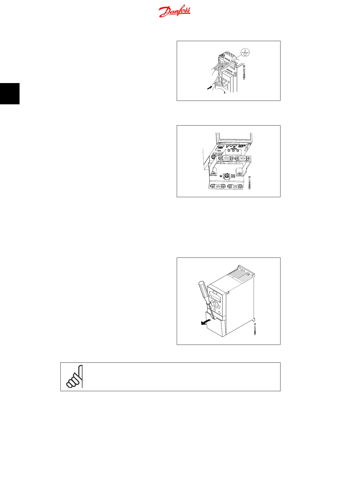
Step 1: First, mount the earth cable.
Step 2: Connect wires to terminals either in
star or delta-connection. See motor name-
plate for further information.
Illustration 3.4: Mounting of earth cable and motor
wires.
For EMC correct installation, use optional de-
coupling plate, see chapter
Options for VLT
Micro Drive FC 51
.
Illustration 3.5: VLT Micro Drive with de-coupling
plate
3.4. Control Terminals
3.4.1. Access to Control Terminals
All control cable terminals are located under-
neath the terminal cover in front of the fre-
quency converter. Remove the terminal cover
using a screwdriver.
Illustration 3.6: Removing terminal cover.
NB!
See back of terminal cover for outlines of control terminals and switches.
3.4.2. Connecting to Control Terminals
This illustration shows all control terminals of the VLT Micro Drive. Applying Start (term. 18) and
an analog reference (term. 53 or 60) make the frequency converter run.
3. Electrical Installation VLT Micro Drive FC 51 Operating Instructions
12
MG.02.A2.02 - VLT
®
is a registered Danfoss trademark
3

 Loading...


