EasyManuals Logo

Danfoss VLT Micro Drive FC 51 Operating Instructions

Danfoss VLT Micro Drive FC 51
37 pages
To Next Page IconTo Next Page
To Previous Page IconTo Previous Page
Page #8 background imageLoading...
Page #8 background image
2.3.1. Mechanical Dimensions
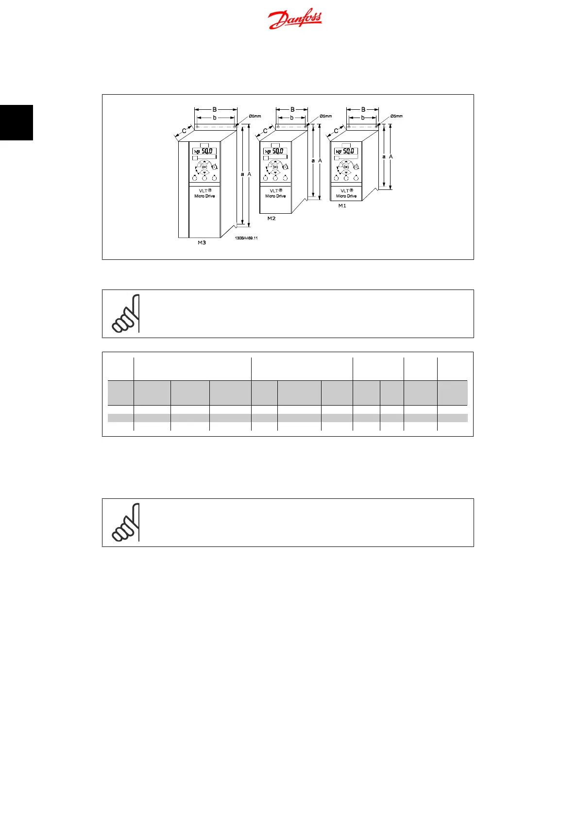
Illustration 2.3: Mechanical dimensions.
NB!
A template for drilling can be found on the flap of the packaging.
Power (kW) Height (mm) Width (mm)
Depth
1)
(mm)
Max.
Weight
Frame
1 X
200-240 V
3 X
200 -240 V
3 X
380-480 V
A
A (incl. de-
coupling
plate)
a B b C Kg
M1 0.18 - 0.75 0.25 - 0.75 0.37 - 0.75 150 205 140.4 70 55 148 1.1
M2 1.5 1.5 1.5 - 2.2 176 230 166.4 75 59 168 1.6
M3 2.2 2.2 -3.7 3.0 - 7.5
2) 2) 2) 2) 2) 2) 2)
Table 2.1: Mechanical Dimensions
1)
For LCP with potentiometer, please add 7.6 mm.
2
These dimensions will be announced at a later point.
NB!
DIN rail mounting kit is available for M1. Please use ordering number 132B0111
2. Mechanical Installation VLT Micro Drive FC 51 Operating Instructions
8
MG.02.A2.02 - VLT
®
is a registered Danfoss trademark
2

Other manuals for Danfoss VLT Micro Drive FC 51

Questions and Answers:

Question and Answer IconNeed help?

Do you have a question about the Danfoss VLT Micro Drive FC 51 and is the answer not in the manual?

Danfoss VLT Micro Drive FC 51 Specifications

General IconGeneral
EnclosureIP20
Output Voltage0-100% of supply voltage
AltitudeUp to 1000 m without derating
Power Range0.18-22 kW
Control MethodV/f
CommunicationModbus RTU
Protection FeaturesOver-voltage, under-voltage, over-current, over-temperature
Ambient Temperature-10°C to 50°C
Storage Temperature-25°C to 65°C
Relative Humidity5-95% (non-condensing)
Input Voltage200-240 V, 380-480 V
Braking FunctionIntegrated braking chopper (optional)

Related product manuals