3.6. Power Circuit - Overview
3.6.1. Power Circuit - Overview
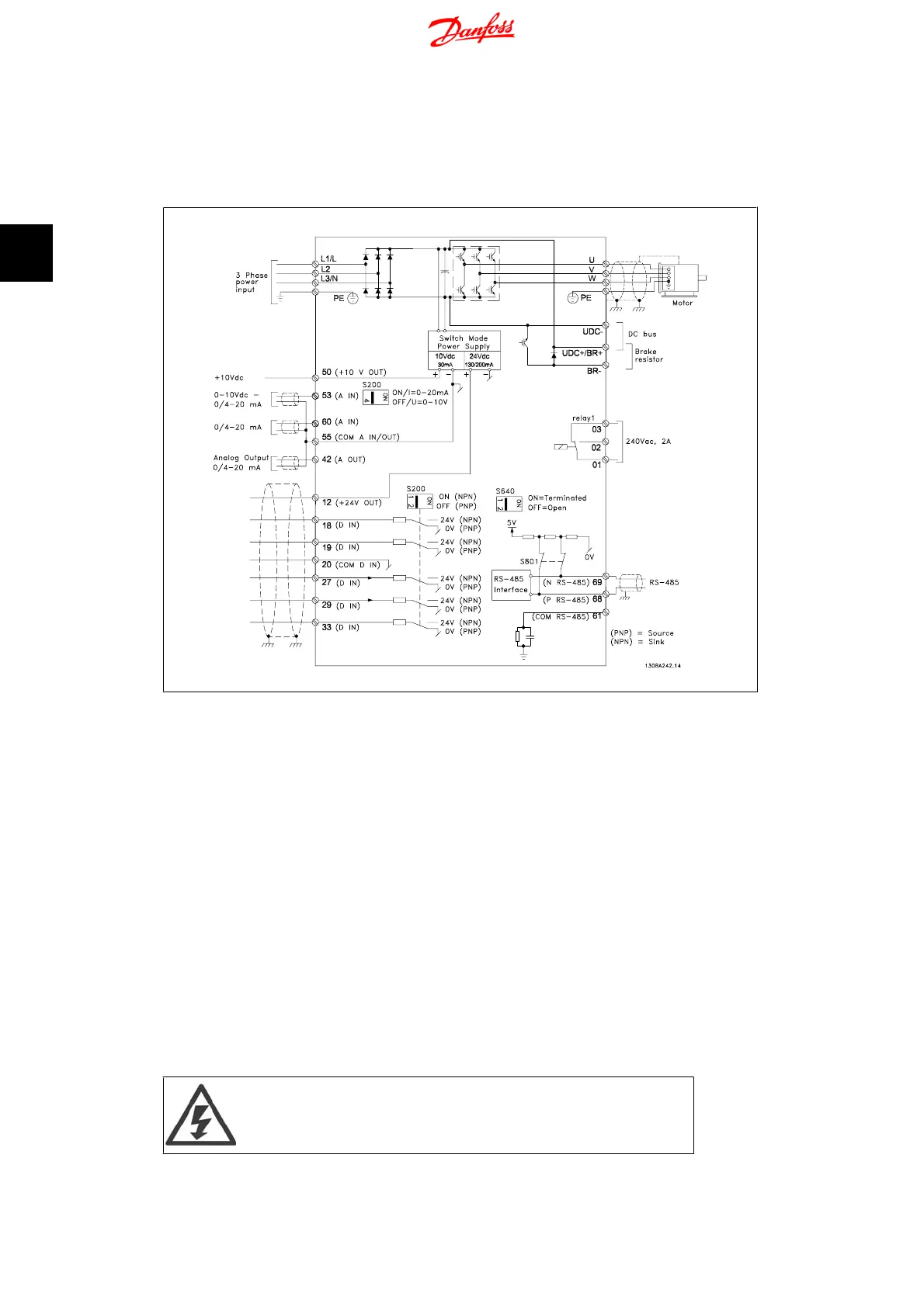
Illustration 3.10: Diagram showing all electrical terminals.
Brake not applicable for frame M1.
Brake resistors are available from Danfoss.
Improved power factor and EMC performance can be achieved by installing optional Danfoss line
filters.
Danfoss power filters can also be used for load sharing.
3.6.2. Load sharing/Brake
Use 6.3 mm insulated Faston Plugs designed for high voltage for DC (Load Sharing and brake).
Contact Danfoss or see instruction no. MI.50.Nx.02 for load sharing and instruction no. MI.90.Fx.
02 for brake.
Load sharing: Connect terminals UDC- and UDC/BR+.
Brake: Connect terminals BR- and UDC/BR+.
Note that voltage levels of up to 850 V DC may occur between terminals
UDC+/BR+ and UDC-. Not short circuit protected.
3. Electrical Installation VLT Micro Drive FC 51 Operating Instructions
14
MG.02.A2.02 - VLT
®
is a registered Danfoss trademark
3

 Loading...


