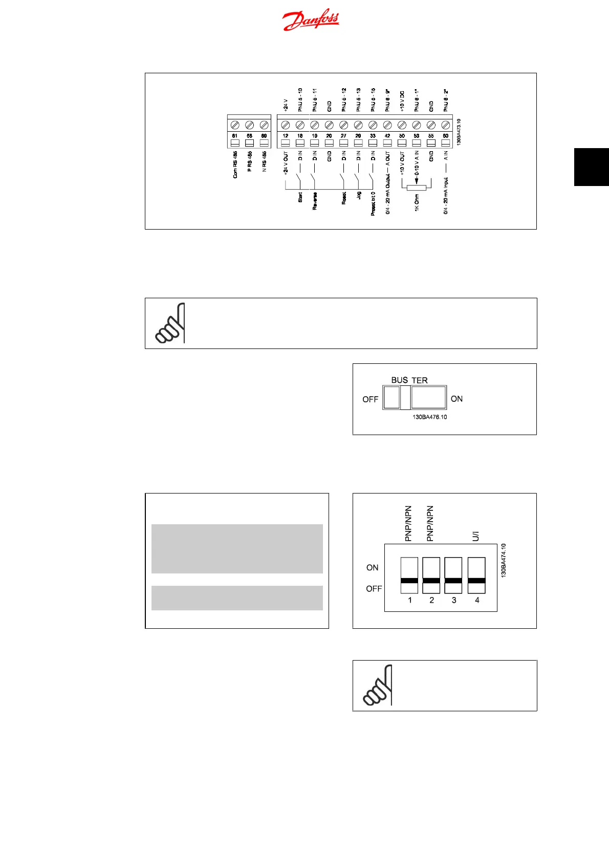
Illustration 3.7: Overview of control terminals in PNP-configuration and factory setting.
3.5. Switches
NB!
Do not operate switches with power on the frequency converter.
Bus termination:
Switch
BUS TER
pos. ON terminates the
RS485 port, terminals 68, 69. See power cir-
cuit drawing.
Default setting = Off.
Illustration 3.8: S640 Bus termination.
S200 Switches 1-4:
Switch 1: *OFF = PNP terminals 29
ON = NPN terminals 29
Switch 2: *OFF = PNP terminal 18, 19, 27
and 33
ON = NPN terminal 18, 19, 27
and 33
Switch 3: No function
Switch 4: *OFF = Terminal 53 0 - 10 V
ON = Terminal 53 0/4 - 20 mA
* = default setting
Table 3.3: Settings for S200 Switches 1-4
Illustration 3.9: S200 Switches 1-4.
NB!
Parameter 6-19 must be set ac-
cording to Switch 4 position.
VLT Micro Drive FC 51 Operating Instructions 3. Electrical Installation
MG.02.A2.02 - VLT
®
is a registered Danfoss trademark
13
3

 Loading...


