EasyManuals Logo

Danfoss VLT Micro Drive FC 51 Operating Instructions

Danfoss VLT Micro Drive FC 51
37 pages
To Next Page IconTo Next Page
To Previous Page IconTo Previous Page
Page #7 background imageLoading...
Page #7 background image
2. Mechanical Installation
2.1. Before Starting
2.1.1. Checklist
When unpacking the frequency converter,
make sure that the unit is undamaged and
complete. Check that the packaging contains
the following:
VLT Micro Drive FC 51
•Quick Guide
Optional: LCP and/or de-coupling plate.
Illustration 2.1: Content of box.
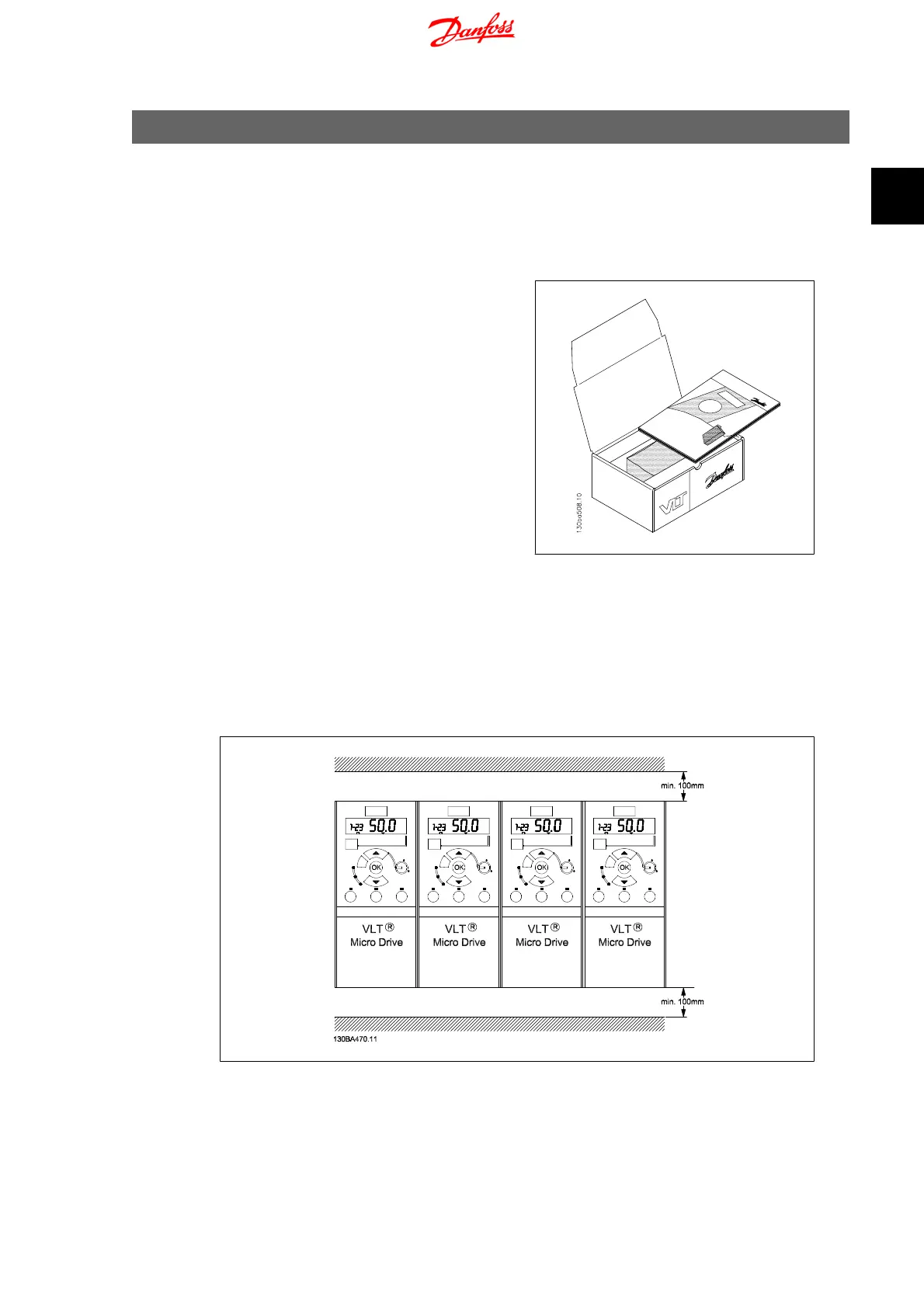
2.2. Side-by-Side Installation
The Danfoss VLT Micro Drive can be mounted side-by-side for IP 20 rating units and requires 100
mm clearance above and below for cooling. Regarding surroundings in general, please see chapter
7. Specifications
.
Illustration 2.2: Side-by-side installation.
VLT Micro Drive FC 51 Operating Instructions 2. Mechanical Installation
MG.02.A2.02 - VLT
®
is a registered Danfoss trademark
7
2

Other manuals for Danfoss VLT Micro Drive FC 51

Questions and Answers:

Question and Answer IconNeed help?

Do you have a question about the Danfoss VLT Micro Drive FC 51 and is the answer not in the manual?

Danfoss VLT Micro Drive FC 51 Specifications

General IconGeneral
EnclosureIP20
Output Voltage0-100% of supply voltage
AltitudeUp to 1000 m without derating
Power Range0.18-22 kW
Control MethodV/f
CommunicationModbus RTU
Protection FeaturesOver-voltage, under-voltage, over-current, over-temperature
Ambient Temperature-10°C to 50°C
Storage Temperature-25°C to 65°C
Relative Humidity5-95% (non-condensing)
Input Voltage200-240 V, 380-480 V
Braking FunctionIntegrated braking chopper (optional)

Related product manuals