NOTICE
Shield all proximity switch sensor/encoder cables. Connect the shield to the chassis at both ends. Always connect the chassis
on the rotary encoder to the chassis of the drive.
NOTICE
EQUIPMENT DAMAGE
Plugging in or pulling off sensor connections during operation can damage the electrical components of the encoder.
-
Always de-energize connected encoders and the safety option before plugging in or pulling off encoder connections.
-
For data signals or track A and track B, use lines twisted in pairs for signal transmission according to RS485.
-
Select the wire cross-section in each individual case in compliance with the current consumption of the encoder and the
cable length required for the installation.
Diagnostics are performed on the encoder input signals. If the encoder diagnostic tests fail, error 99 (Safe State Fault) occurs.
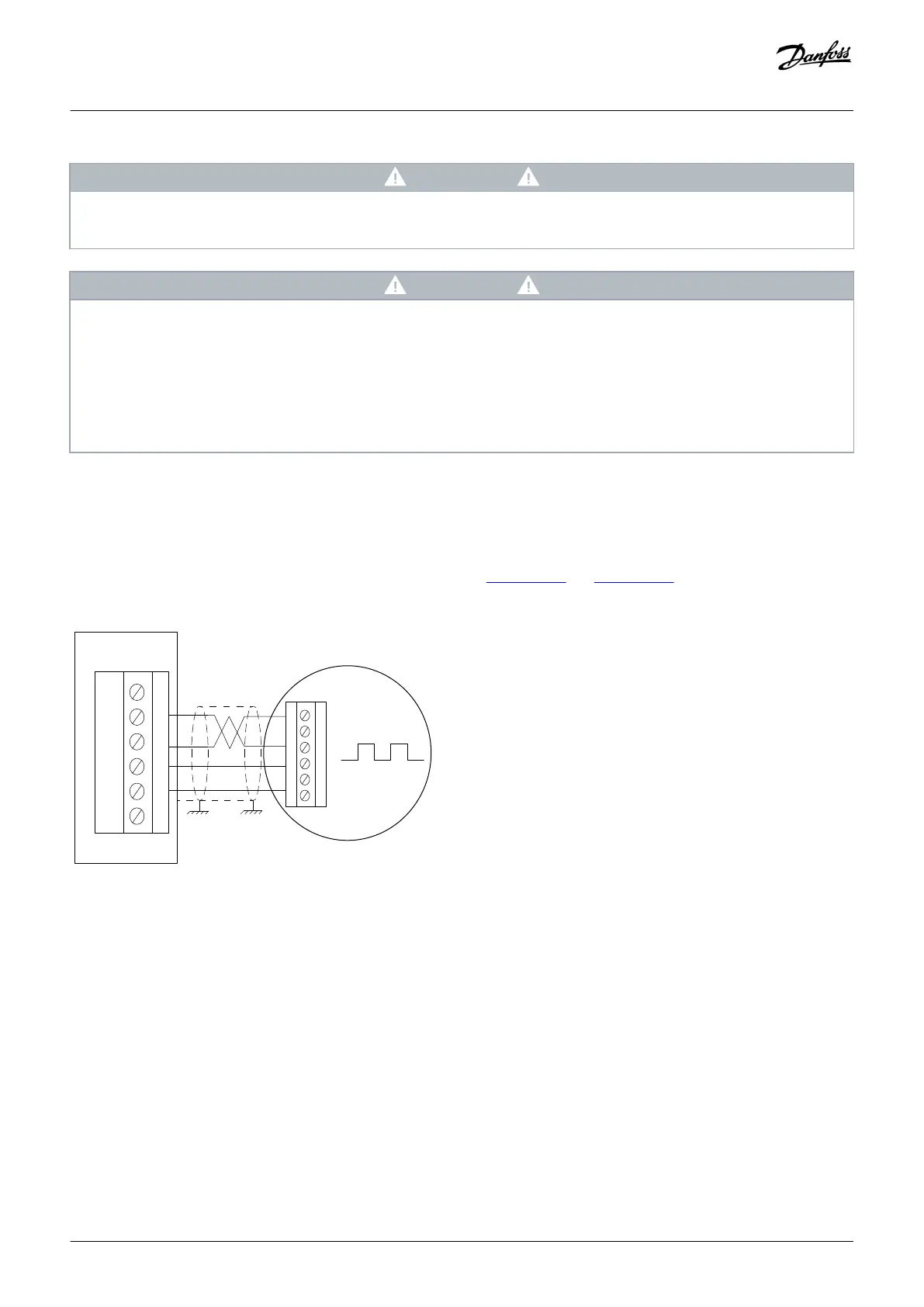
4.2.2 Encoder Wiring Examples
See examples of how to connect encoder power and encoder signals in illustration 25 and illustration 26.
Illustration 25: Y31/Connecting Power and Encoder Signals to HTL Encoder (VLT® Safety Option MCB 151)
Installation
Installation Guide | VLT® Safety Option MCB 150/151
AQ279747441421en-000101 / 130R0292 | 45
Danfoss A/S © 2018.09
 Loading...