7-14
VLT is a registered Danfoss trademark
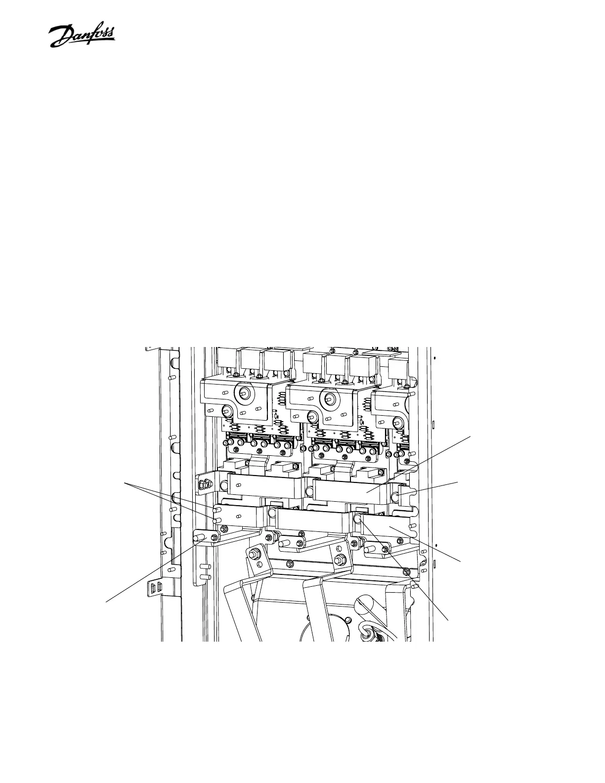
Figure 7-12. IGBT Modules (2 of 4)
Load sharing option
retaining studs
(Step 8)
Positive (+) output bus bar
BB42 (Step 9)
Positive (+) output bus
bar connecting screw
(Step 9)
Negative (-) output bus bar
BB42 (Step 9)
Negative (-) output bus
bar connecting screw
(Step 9)
SCR and Diode
input bus bar BB41
(Step 10)
8. If unit is not equipped with load sharing option,
proceed to step 9. If unit is equipped with load
sharing, load share minus (-) bus bar must be
removed as follows.
a. Remove 2 retaining nuts (13 mm) connecting
load share bus bar to the SCR output bus bar.
b. Remove retaining nut (17 mm) connecting
load share bus bar to load share terminal on
opposite end of bus bar (not shown).
c. Remove load share bus bar.
9. Remove both positive (+) and negative (-) SCR
output bus bars by removing 6 connection screws
(T50). There are 3 screws per bus bar.
10. Remove three SCR and Diode input bus bars by
removing 6 connection screws (T50). There are 2
screws per bus bar.
CONTINUED NEXT PAGE

 Loading...


