EasyManuals Logo

Danfoss VLT series Service Manual

Danfoss VLT series
158 pages
To Next Page IconTo Next Page
To Previous Page IconTo Previous Page
Page #137 background imageLoading...
Page #137 background image
7-15
VLT is a registered Danfoss trademark
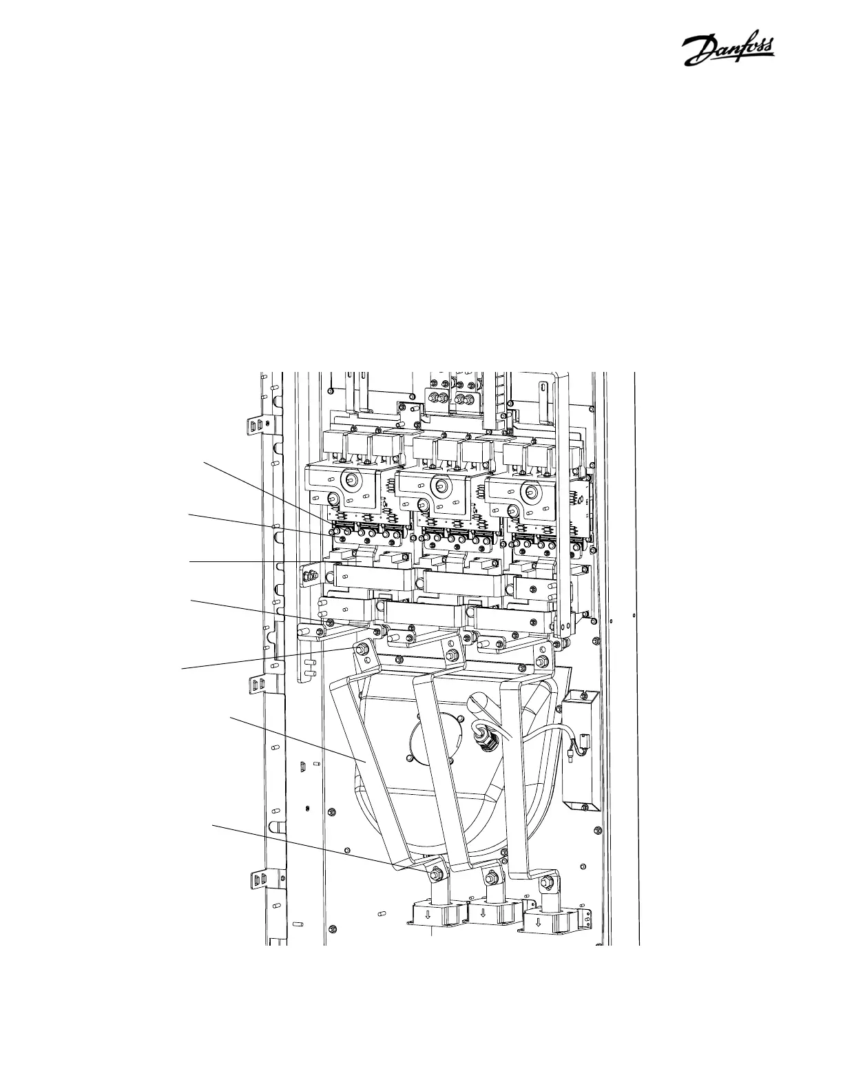
Figure 7-12. IGBT Modules (3 of 4)
11. Remove 6 retaining screws (T30) connecting each
IGBT module output to IGBT output bus bars.
12. Remove retaining nut (17 mm) connecting IGBT
output bus bar to IGBT over-fan bus bar. Note
that there is one for each of three phases.
13. Remove retaining nut (17 mm) or T50 Torx screw,
depending on unit type, connecting IGBT over-fan
bus bar to current sensor bus bar.
Output bus bar
Retaining screw
(Step 11)
Retaining nut
(Step 12)
Retaining nut
(Step 13)
Over-fan bus bar
Retaining nut
(Step 14)
14. Remove 3 retaining nuts (17 mm) at top and one
retaining nut (8 mm) at bottom attaching IGBT
output bus bar to standoffs. Remove IGBT output
bus bar.
CONTINUED NEXT PAGE
Retaining nut
(Step 14)

Table of Contents

Other manuals for Danfoss VLT series

Questions and Answers:

Question and Answer IconNeed help?

Do you have a question about the Danfoss VLT series and is the answer not in the manual?

Danfoss VLT series Specifications

General IconGeneral
SeriesVLT
CategoryDC Drives
Output Voltage0-100% of input voltage
Protection FeaturesOvervoltage, Undervoltage, Overcurrent, Overtemperature, Short Circuit, Ground Fault
Communication InterfacesProfibus, CANopen
Enclosure RatingIP20, IP21, IP55, IP66
Cooling MethodForced Air Cooling, Convection Cooling
Control ModeSensorless Vector, Closed Loop Vector
Ambient Temperature-10°C to +50°C (14°F to 122°F)

Related product manuals