8-3
VLT is a registered Danfoss trademark
Pin
No.
Schematic
Acronym
Function Description Reading Using a Digital
Volt Meter
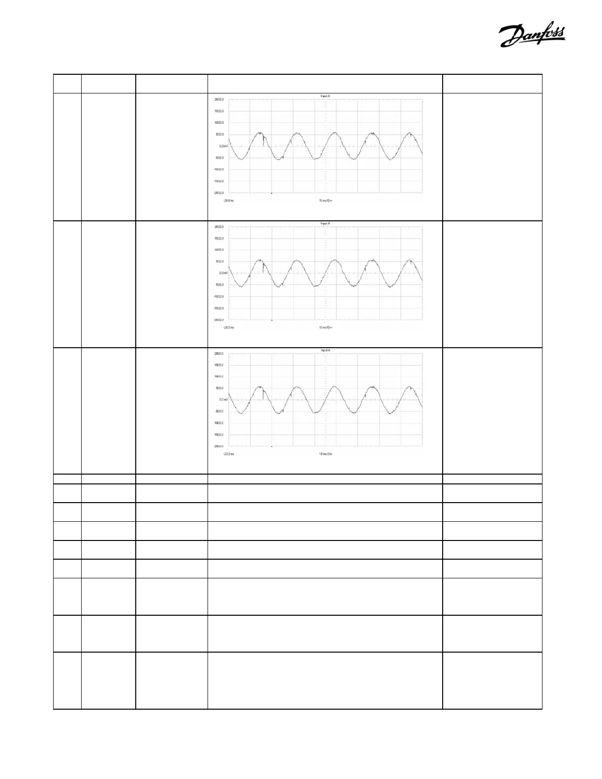
1 IU1 Current sensed,
U phase, not
conditioned
Approx 400mv RMS @100% load
.937 VACpeak @ 165%
of CT current rating. AC
waveform @ output
frequency of the drive.
2 IV1 Current sensed,
V phase, not
conditioned
Approx 400mv RMS @100% load
.937 VACpeak @ 165%
of CT current rating. AC
waveform @ output
frequency of the drive.
3 IW1 Current sensed,
W phase, not
conditioned
Approx 400mv RMS @100% load
.937 VACpeak @ 165%
of CT current rating. AC
waveform @ output
frequency of the drive.
4 COMMON Logic common This common is for all signals.
5 AMBT Ambient temp. Used to control FAN high and low fan speeds. 1VDC approximately
equal to 25C
6 FANO Control Card
signal
Signal from Control Card to turn fans on and off. 0VDC – ON command
5VDC – OFF command
7 INRUSH Control Card
signal
Signal from Control Card to start gating SCR front end 5VDC – SCRs disabled
0VDC – SCRs enabled
8 RL1 Control Card
signal
Signal from Control Card to provide status of Relay 01 5VDC – Relay active
0VDC – inactive
9 EXT24V Signal to Control
Card
Signal indicating a backup power supply is active. 5VDC – backup present
0VDC – no backup
10 TEMP_HS Analog signal
inversely
proportional to
HS temp
Will read ~ 3.3 volts if the heat sink NTC is disconnected. As
HS temperature goes up the voltage goes down.
Formula, VDC = 2.82 –
0.035 * (T – 30), where
T is the temperature in
degrees Celsius.
11 VPOS +18 VDC
regulated supply
+16.5 to 19.5
VDC
Red LED indicates voltage is present between VPOS and
VNEG terminals.
+18 VDC regulated
supply +16.5 to 19.5
VDC
12 VNEG -18 VDC
regulated supply
-16.5 to 19.5
VDC
Red LED indicates voltage is present between VPOS and
VNEG terminals.
-18 VDC regulated
supply
-16.5 to 19.5 VDC

 Loading...


