8-4
VLT is a registered Danfoss trademark
Pin
No.
Schematic
Acronym
Function Description Reading Using a Digital
Volt Meter
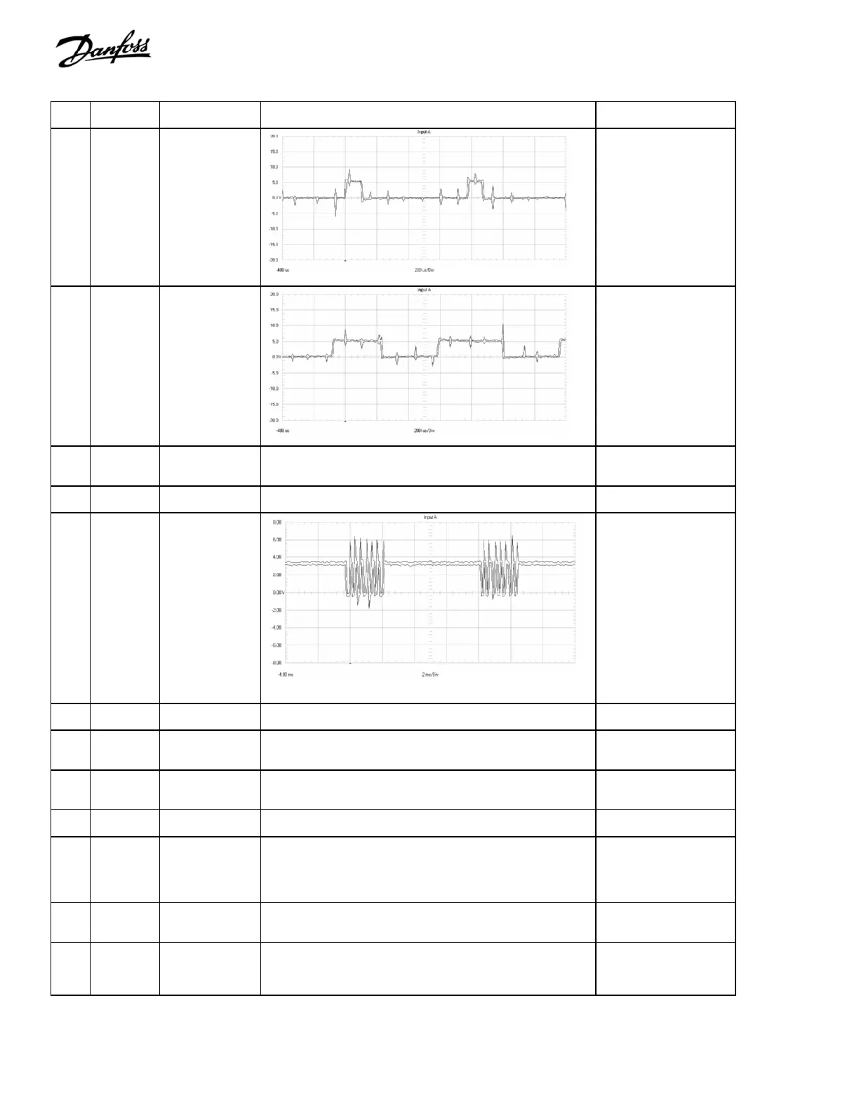
13 DBGATE Brake IGBT gate
pulse train.
(Signal to brake
IGBT.)
Varies w/ brake duty cycle
Voltage drops to zero
when brake is turned off.
Voltage increases to
4.04 VDC as brake duty
cycle reaches max.
14 BRT_ON Brake IGBT 5V
logic level signal.
(Indicates
voltage across
brake IGBT.)
Varies w/ brake duty cycle
5.10 VDC level with the
brake turned off.
Voltage decreases to
zero as brake duty cycle
reaches max.
15 OTFLT Temperature /
Voltage out of
range
Monitors Brake resistor, Heatsink temp, Ambient temp, power
supplies voltages.
5VDC – No fault
0VDC – Fault
16 FAN_TST Control signal for
fans
Indicates Fan Test switch is activated to force the fans on high +5VDC – disabled
0VDC – fans on high
17 FAN_ON Pulse train to
gate SCR’s for
fan voltage
control. In sync
with line freq.
7 trigger pulses at 3Khz
5VDC - fans off
~4.3VDC – fans on
18 HI_LOW Control signal
from Power Card
Signal to switch fan speeds between high and low +5VDC = fans on high,
Otherwise 0VDC.
19 SCR_DIS Control signal for
SCR front end
Indicates SCR front end is enabled or disabled. 0.6 to 0.8 VDC – SCRs
enabled
0VDC – SCR disabled
20 INV_DIS Control signal
from Power Card
Disables IGBT gate voltages 5VDC – inverter
disabled
0VDC – inverter enabled
21 RFI_RL2 Control signal for
RFI
Ground signal to enable RFI HF capacitors 24VDC – no RFI
0VDC – RFI enabled
22 UINVEX Bus Voltage
scaled down
Signal proportional to UDC 380- 500 V
1VDC = 262 VDC
525 – 690 V
1VDC = 373 VDC
OV switch must be off.
23 VDD +24 VDC power
supply
Yellow LED indicates voltage is present. +24 VDC regulated
supply
+23 to 25 VDC
24 VCC +5.0 VDC
regulated supply.
+4.75-5.25 VDC
Green LED indicates voltage is present. +5.0 VDC regulated
supply +4.75 to 5.25
VDC

 Loading...


