3.6.2 Creating an Entry for Cables
Cables are connected from the bottom of the pedestal, through a metal gland plate, and into the cabinet. The gland plates
must be tted to the unit to ensure the specied degree of protection.
1. Open the mains cabinet and remove the nuts from the mains gland plate. Remove the plate.
2. Open the motor cabinet and remove the nuts from the motor gland plate. Remove the plate.
3. Use a sheet metal punch to create entry holes in the mains and motor plates. Refer to the gland plate dimensions
in chapter 5.2 Dimensions.
4. Reattach the mains and motor gland plates after the unit has been lowered onto the pedestal, as shown in
Illustration 3.10.
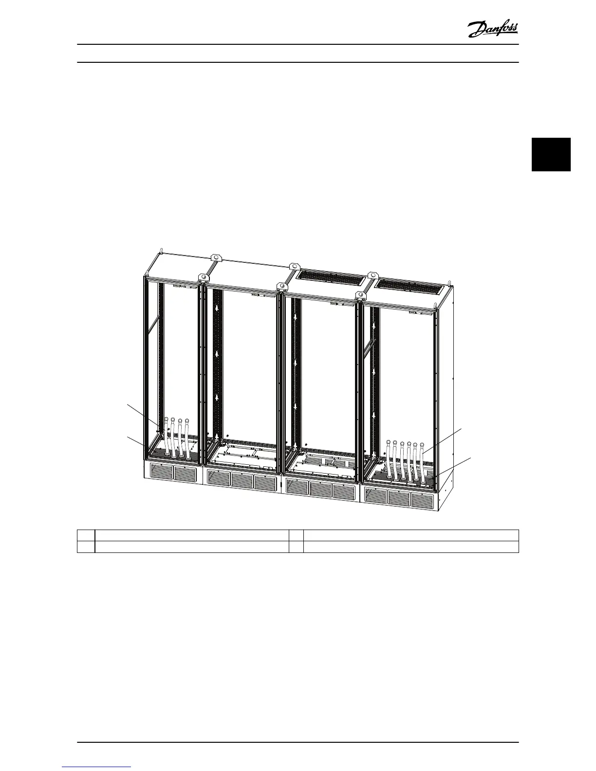
1 Motor cables. 3 Mains gland plate. See chapter 5.2 Dimensions.
2 Motor gland plate. See chapter 5.2 Dimensions. 4 Mains cables.
Illustration 3.10 Cable Entry through the Gland Plates (Example)
Mechanical Installation Installation Guide
MG13B102 Danfoss A/S © 09/2015 All rights reserved. 19
3 3

 Loading...


