See Installation of Duct Cooling Kit in Rittal Enclosures, for
further information.
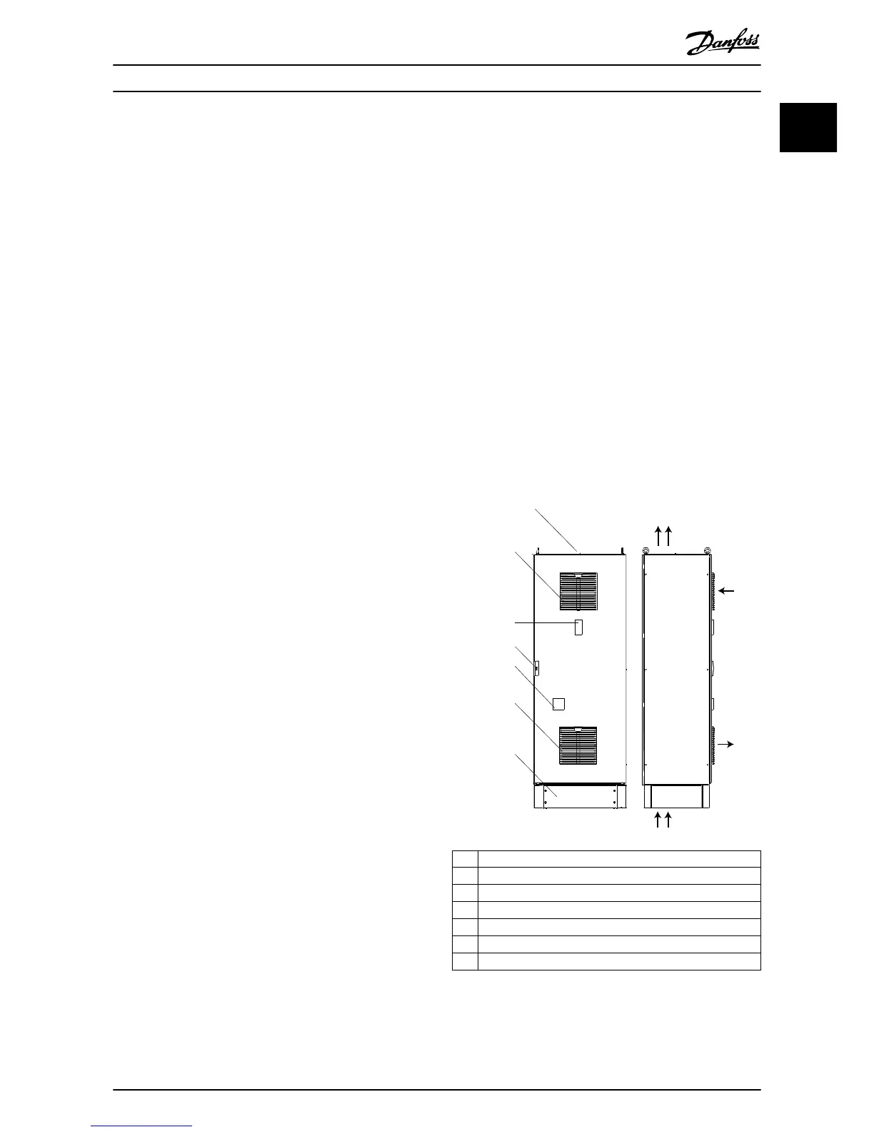
The remaining heat losses are handled via fans and lter
combinations in the VLT
®
Plus Panel front doors.
Door fan
One or more door fans remove the heat losses not
contained in the frequency converter backchannel and any
additional losses generated from other components
installed inside the enclosure. The total required air ow is
calculated with a dedicated software tool and the required
air ow is shown in the panel documentation.
The frequency converter fan runs for the following reasons:
•
AMA.
•
DC hold.
•
Pre-mag.
•
DC brake.
•
60% of nominal current is exceeded.
•
Specic heat sink temperature exceeded (power
size dependent).
•
Specic power card ambient temperature
exceeded (power size dependent).
•
Specic control card ambient temperature
exceeded.
Once the frequency converter fan is started, it runs for
minimum 10 minutes.
The door fans run, whenever the thermostat inside the
panel reaches the adjusted limit. Once the o-setpoint is
reached, it switches the fans o. The duration of the on-
time varies and depends on the load and local conditions,
as well as on the pollution of the air lters.
Cabinet light with power outlet
A light mounted on the cabinet interior increases visibility
during servicing and maintenance. The light housing
includes a power outlet (230 V, 50 Hz, 2.5 A, CE/ENEC) for
temporarily supplying power to tools or other devices.
Transformer taps
The auxiliary supply transformer is factory-set to the
nominal supply voltage of the cabinet. The transformer
taps can be adjusted to the local conditions, to avoid over-
and undervoltage. Additional information is provided in
the documentation for the optional transformer.
Optional 24 V DC supply
•
Specications: 5 A, 120 W, 24 V DC.
•
Purpose: Supplying power for customer-supplied
accessory devices, such as:
- Sensors.
- PLC I/O.
- Contactors.
- Temperature probes.
- Indicator lights.
- Other electronic hardware used for
internal control/auxiliary circuits.
•
Protected against output overcurrent, overload,
short circuits, and overtemperature.
•
Diagnostics include a dry DC-ok contact, a green
DC-ok indicator light, and a red overload
indicator light.
1.4.3 Product Variant Examples

 Loading...


