3.6.3 Attaching the Unit to the Pedestal
CAUTION
IMPROPER ALIGNMENT
Improper alignment and insucient installation, can
cause damage to the unit and injury.
Only qualied and authorised personnel shall do this
installation.
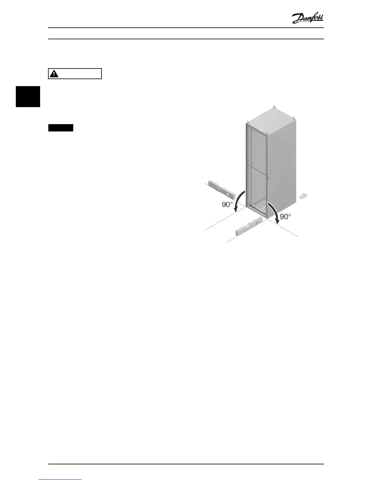
NOTICE
Illustration 3.12 shows an example. The procedure to be
applied depends on the surface the unit is mounted to,
and is therefore application-specic. The procedure
described here shows the general principle.
1. Lift the unit and position it on the pedestal. Refer
to chapter 3.5.3 Lifting the Unit.
2. Verify that there is 225 mm (9 in) top clearance
for air exhaust.
3. Verify that the air intake from the bottom of the
unit is not obstructed.
4. Make sure that the unit is aligned to the surface
and the surrounding units. Refer to
Illustration 3.11.
5. Install each M8x60 mm bolt with lock washer and
at washer through the frame into the threaded
hole in the base. Install 4 bolts per cabinet. Refer
to Illustration 3.12.
6. Install each M10x30 mm bolt with captive lock
washer and at washer through the base plate
and into the threaded hole in the base. Install 4
bolts per cabinet. Illustration 3.12.

 Loading...


