4.4 Fuses
4.4.1 Motor Insulation
For motor cable lengths ≤ the maximum cable length
listed in chapter 5
Specications, the recommended motor
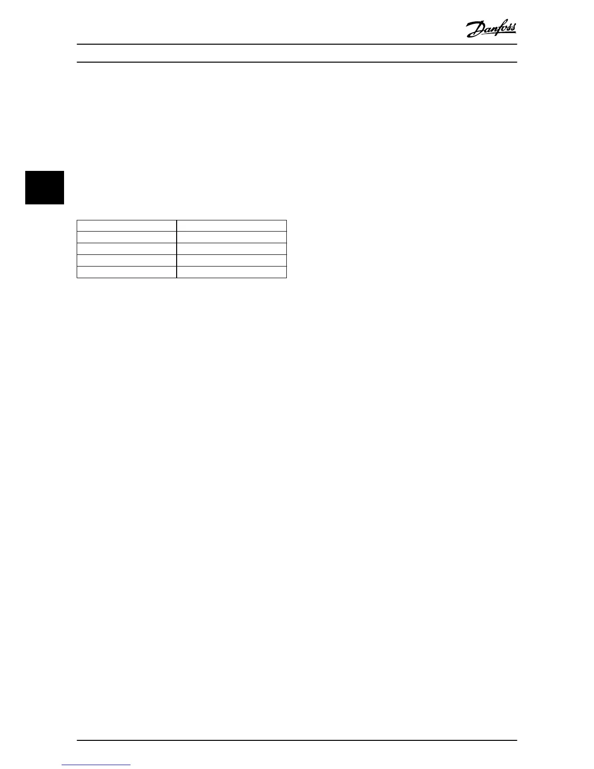
insulation ratings are in Table 4.1. The peak voltage can be
up to twice the DC-link voltage, 2.8 times the mains
voltage, due to transmission line eects in the motor cable.
If a motor has a lower insulation rating, use a dU/dt or sine
wave lter.
Nominal mains voltage Motor insulation
U
N
≤420 V
Standard U
LL
= 1300 V
420 V <U
N
≤500 V Reinforced U
LL
= 1600 V
500 V <U
N
≤600 V Reinforced U
LL
= 1800 V
600 V <U
N
≤690 V Reinforced U
LL
= 2000 V
Table 4.1 Motor Insulation at Various Nominal Mains Voltages
4.4.2 Motor Bearing Currents
All motors installed with FC 302 90 kW or higher power
frequency converters should have NDE (non-drive end)
insulated bearings installed to eliminate circulating bearing
currents. To minimize DE (drive end) bearing and shaft
currents, proper grounding of the frequency converter,
motor, driven machine, and motor to the driven machine is
required.
Standard mitigation strategies:
1. Use an insulated bearing.
2. Apply rigorous installation procedures.
2a Ensure that the motor and load motor
are aligned.
2b Strictly follow the EMC installation
guideline.
2c Reinforce the PE so the high frequency
impedance is lower in the PE than the
input power leads.
2d Provide a good high frequency
connection between the motor and the
frequency converter. Achieve that for
example by using a screened cable
which has a 360° connection in the
motor and the frequency converter.
2e Make sure that the impedance from
frequency converter to building ground
is lower than the grounding impedance
of the machine. This can be dicult for
pumps.
2f Make a direct ground connection
between the motor and load motor.
3. Lower the IGBT switching frequency.
4.
Modify the inverter waveform, 60° AVM versus
SFAVM.
5. Install a shaft grounding system or use an
isolating coupling.
6. Apply conductive lubrication.
7. Use minimum speed settings if possible.
8. Try to ensure that the line voltage is balanced to
ground. This can be dicult for IT, TT, TN-CS or
grounded leg systems.
9. Use a dU/dt or sinus lter.
4.4.3 Control Cable Routing
Tie down all control wires to the designated control cable
routing. To ensure optimum electrical immunity, connect
the screens properly.
Fieldbus connection
Connections are made to the relevant options on the
control card. For details, see the relevant eldbus
instruction. Place the cable in the provided path inside the
frequency converter and tie it down with other control
wires.
Electrical Installation
VLT
®
Plus Panel
28 Danfoss A/S © 09/2015 All rights reserved. MG13B102
44

 Loading...


