EasyManuals Logo

Danfoss VLT series Installation Guide

Danfoss VLT series
40 pages
To Next Page IconTo Next Page
To Previous Page IconTo Previous Page
Page #29 background imageLoading...
Page #29 background image
PE
U
V
W
10
6
8
9
7
3
4
130BD628.11
2
1
5
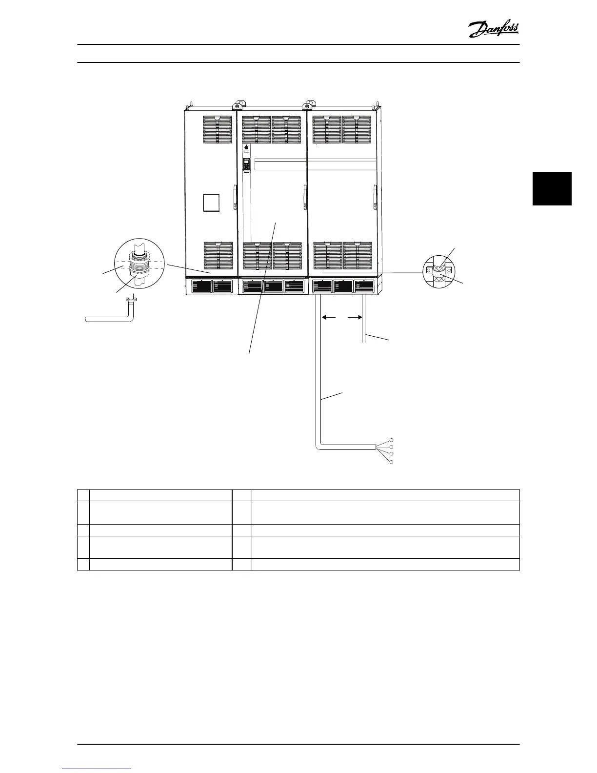
1 Stripped cable insulation 6 Motor cable, 3-phase cables, and ground
2 Clamped screen-to-ground point inside
cabinet
7 To prevent ground loops due to variations in ground potential, t an equalizing
cable next to the control cable. Minimum cable cross-section is 16 mm
2
(4 AWG)
3 Control cables 8 Mains cable, 3-phase cables, and reinforced ground
4 Minimum 200 mm (7.9 in) between control
cables, motor cable, and mains cable
9 EMC cable gland
5 Screened cable 10 Gland plate
Illustration 4.1 Proper EMC Installation
Electrical Installation Installation Guide
MG13B102 Danfoss A/S © 09/2015 All rights reserved. 27
4 4

Other manuals for Danfoss VLT series

Questions and Answers:

Question and Answer IconNeed help?

Do you have a question about the Danfoss VLT series and is the answer not in the manual?

Danfoss VLT series Specifications

General IconGeneral
SeriesVLT
CategoryDC Drives
Output Voltage0-100% of input voltage
Protection FeaturesOvervoltage, Undervoltage, Overcurrent, Overtemperature, Short Circuit, Ground Fault
Communication InterfacesProfibus, CANopen
Enclosure RatingIP20, IP21, IP55, IP66
Cooling MethodForced Air Cooling, Convection Cooling
Control ModeSensorless Vector, Closed Loop Vector
Ambient Temperature-10°C to +50°C (14°F to 122°F)

Related product manuals