*Terminal 37 (optional) is used for Safe Torque O. For Safe Torque O installation instructions, refer to the VLT
®
Frequency
Converters Safe Torque O Operating Instructions.
EXTERNAL BRAKE
FUSE
A2
W
W
U
U
V
V
W
U
V
C14
C13
117118
+ -
EXTERNAL BRAKE
EXTERNAL BRAKE
EXTERNAL BRAKE
CONTROL CARD PIN 20
(TERMINAL JUMPERED TOGETHER)
CUSTOMER SUPPLIED
(TERMINAL JUMPERED TOGETHER)
MCB 113 PIN X46/1
MCB 113 PIN X46/3
MCB 113 PIN X46/5
MCB 113 PIN X46/7
MCB 113 PIN X46/9
MCB 113 PIN X46/11
MCB 113 PIN X46/13
MCB 113 PIN X47/1
MCB 113 PIN X47/3
MCB 113 PIN X47/2
MCB 113 PIN X47/4
MCB 113 PIN X47/6
MCB 113 PIN X47/5
MCB 113 PIN X47/7
MCB 113 PIN X47/9
MCB 113 PIN X47/8
MCB 113 PIN X45/1
MCB 113 PIN X45/2
MCB 113 PIN X45/3
MCB 113 PIN X45/4
AUX FAN AUX FAN
TB3 INVERTER 2
TB3 INVERTER 2
R-
R-
R+
R+
TB3 INVERTER 1
TB3 INVERTER 1
PILZ
TERMINALS
REGEN
TERMINALS
MCB 113 PIN 12
MCB 112 PIN 1
MCB 112 PIN 2
CONTROL CARD PIN 37
CONTROL CARD PIN 53
CONTROL CARD PIN 55
TB08 PIN 01
TB08 PIN 02
TB08 PIN 04
TB08 PIN 05
1
1
1
1
2
2
3
3
4
5
5
3
3
10
12
13
14
15
16
17
18
30
31
32
33
34
35
36
37
38
39
40
41
42
50
51
60
61
62
63
90
91
11
TB7
L1 L1
L2 L2
100 101 102
81
81
2
1
3
96
96
96
97
97
97
98
98
TB4
TB8
98
82
82
103
CUSTOMER
SUPPLIED 24V RET.
CUSTOMER
SUPPLIED 24V
130BB760.11
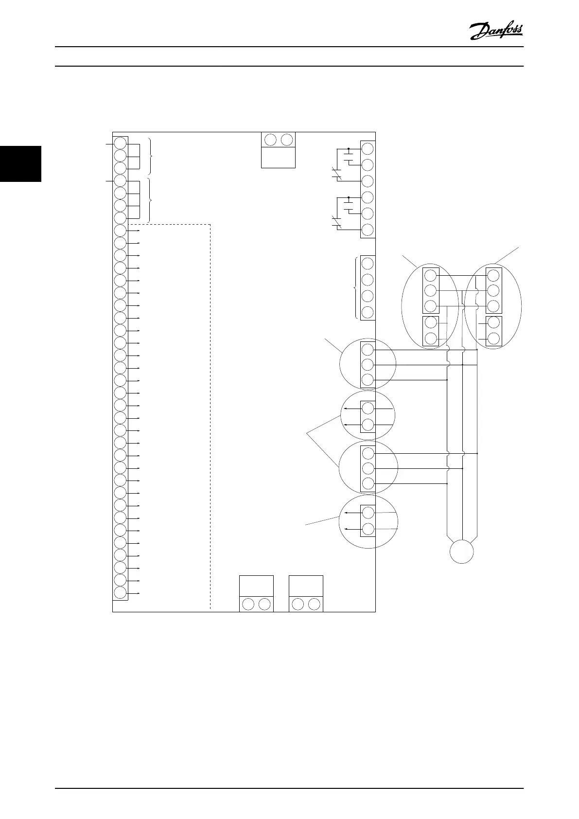
NAMUR Terminal Denition
2
81
82
EXTERNAL BRAKE
EXTERNAL BRAKE
W
U
V
4
96
97
98
81
82
R-
R+ R+
R-
Illustration 3.51 Diagram Showing all Electrical Terminals with NAMUR Option
How to Install
VLT
®
AutomationDrive FC 302
54 Danfoss A/S © 04/2016 All rights reserved. MG34Q402
33