System Installation and Configuration
96-30051-001 Rev. D3 DDN SFA12K (SFA OS 2.3.1) Hardware Installation & Configuration Guide | 30
9.1 Powering On using the Controller Power Button
If you turn on the controller by pressing only the controller power button, the controller will
automatically turn on its dedicated BBU once the controller is completely up and running.
Note that if you take this approach, you will not be able to verify that the BBU is on until that
point.
This feature is available:
• To ensure that the controller’s BBU is running even if you forget to turn it on
• To provide the ability to turn on the controller with a single push button
• To allow the controller and its BBU to be restarted remotely via IPMI
10. Serial Interface Setup & Accessing the CLUI
The SFA12K can be configured and administered either via serial connection (using the
supplied serial cable) or via Ethernet connection. However, in order to use the Ethernet
connection, it is first necessary to configure the network settings on each controller. This
can only be done using the serial interface as described in Section 11. The RS-232 console
can also be used to log the console output and to upgrade the BIOS/BMC firmware.
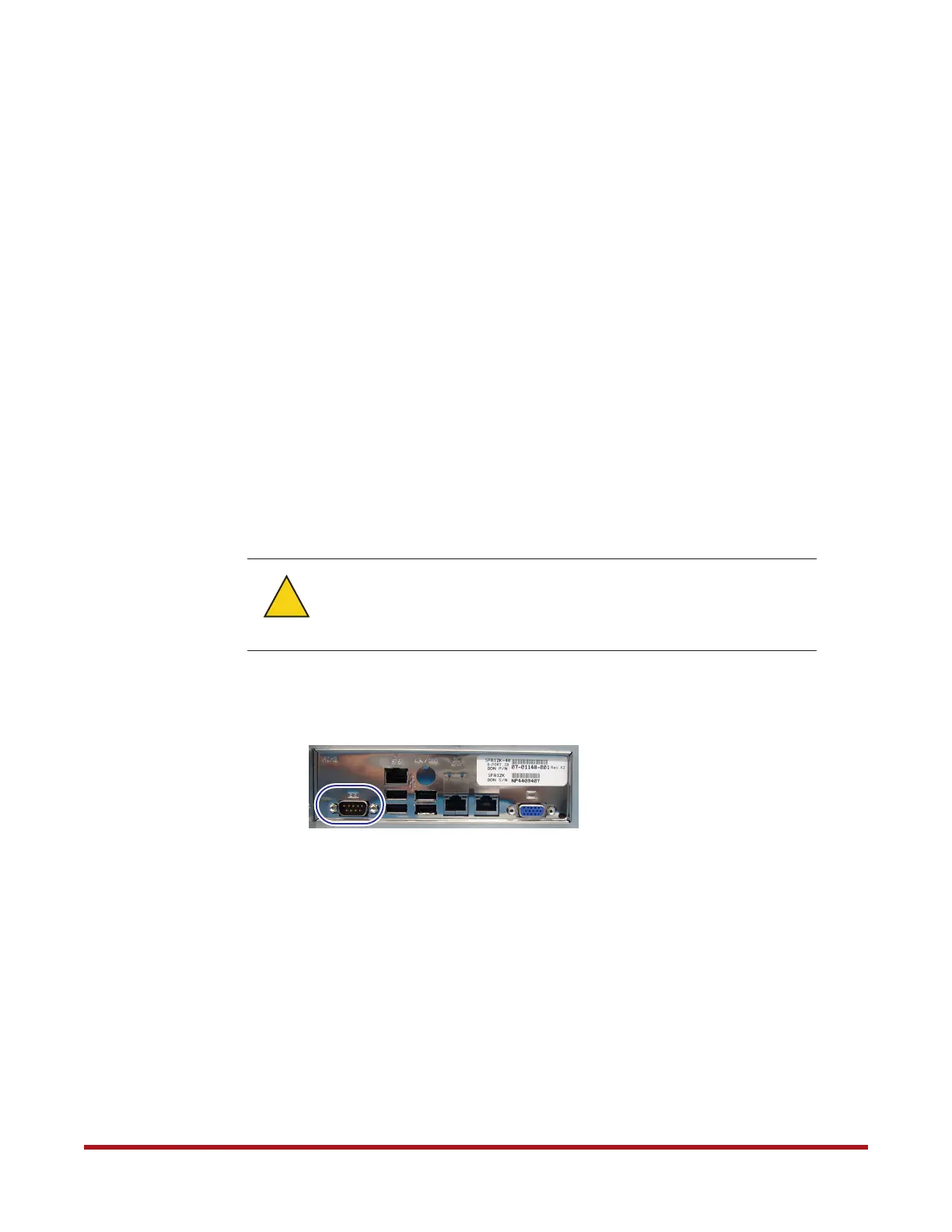
1. Connect a null modem cable between a PC and the RS-232 connector on the back of the
controller (Figure 26).
2. On the RS-232 console, load a serial console program (such as HyperTerminal,
minicom, PuTTY, or screen) and use the following settings for the serial connection:
❖ Bits per second: 115,200
❖ Data bits: 8
❖ Parity: None
❖ Stop bits: 1
❖ Flow control: None
3. Once connected, press the <Enter> key to bring up the login prompt. Enter the user
name user and password user.
The CLUI commands are independent of case. Most of the keywords can be abbreviated and
most of the punctuations are optional.
When the RS-232 null modem cable is attached to the controller, its
corresponding opposite cable end must always be connected to a PC or
properly terminated. It should not be left unterminated or the operation
of the controller may be affected.
Warning
!
Figure 26. RS-232 Port on Controller