INSTALLATION
2
2.3.3 Ethernet Connector
This connector is only available for DX8200A Ethernet models and allows the Ethernet
connection between the host and the reader.
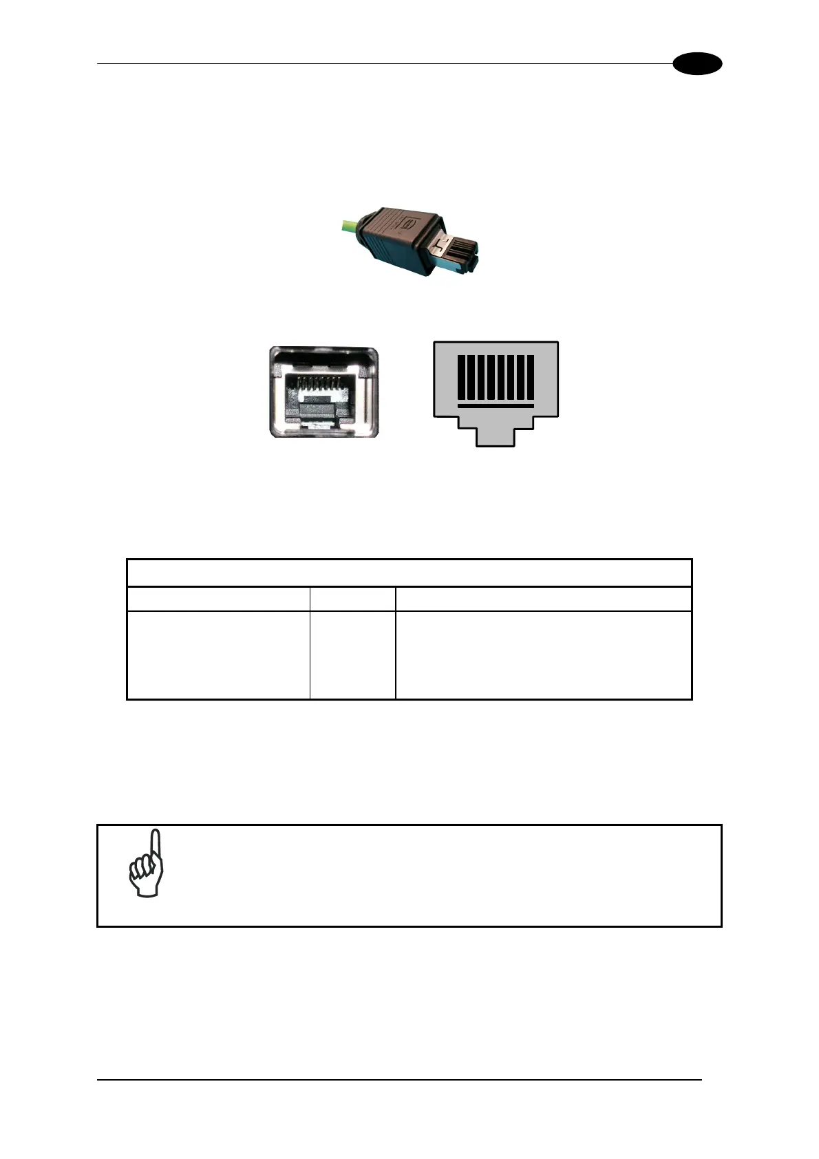
Figure 23 – Harting RJ Industrial® Push Pull Male Connector
1
8
Figure 24 – DX8200A Harting RJ Industrial® Female Connector
This interface and the connector pinout (see the following table) are IEEE 802.3 10 BaseT
and IEEE 802.3u 100 Base Tx compliant.
RJ45 Modular Jack Pinout
Pin Name Function
1 TX + Transmitted data (+)
2 TX - Transmitted data (-)
3 RX + Received data (+)
6 RX - Received data (-)
4, 5, 7, 8 N.C. Not connected
In order to meet EMC requirements:
• use Eth shielded cable
• connect the Ethernet interface cable shield to the plant earth ground
NOTE
A ferrite (type Stewart 28A2029-0A0) must be applied on the scanner side
of the Ethernet cable to reduce electrical noise. The cable shield must
also be connected to the chassis of both connectors.
21
 Loading...