Appendix J – General Purpose Input Output Ports
228 Class Series Programmer’s Manual
Each GPIO pin function is detailed in the table below:
M-Class GPIO Port Overview
Pin
Number(s)
Signal
Name
Signal
State
Signal
Direction
[1]
Signal Description
[2]
1Vcc
+5 VDC @
2.5 Amp (fused )
Output Printer +5 VDC
2 Printer Fault Low Output
Goes low if the printer detects a fault and
applies only when not equipped with a
cutter. To activate set the GPIO Equipped
to “A” and Cutter Equipped to “NO”.
3 Spare Reserved Input
Must be pulled high (see sample SOP
circuit, below).
4
Start of Print
(SOP)
Programmable Input
When active, will begin print. Recommend
only setting this signal to ACTIVE LOW.
When ready to print a label, the applicator
should hold this signal low for at least
50ms – or until EOP goes not active. See
sample SOP circuit, below.
5
End of Print
(EOP)
Programmable Output
Signifies the end of the print process. Can
be monitored to initiate next Start of Print
sequence. Minimum signal time 30ms.
6 & 8 Signal Ground Ground N/A Ground
7+24 VDC
+24 VDC @
1.6 Amp (fused )
Output Printer +24 VDC
[1]
Given relative to the printer.
[2]
The operation of this multi-function port is configuration dependent: Non-Display models use the <STX>Kc or program the
selections via the “Printer Setup Menu List,” disable all unused optional functions (i.e., present sensor, cutter, etc.), and set
GPIO to “YES”; or, for Display-Equipped models via the “Menu System” go to Options / GPIO / Applicator and select
Enable. See the Operator’s Manual for more details.
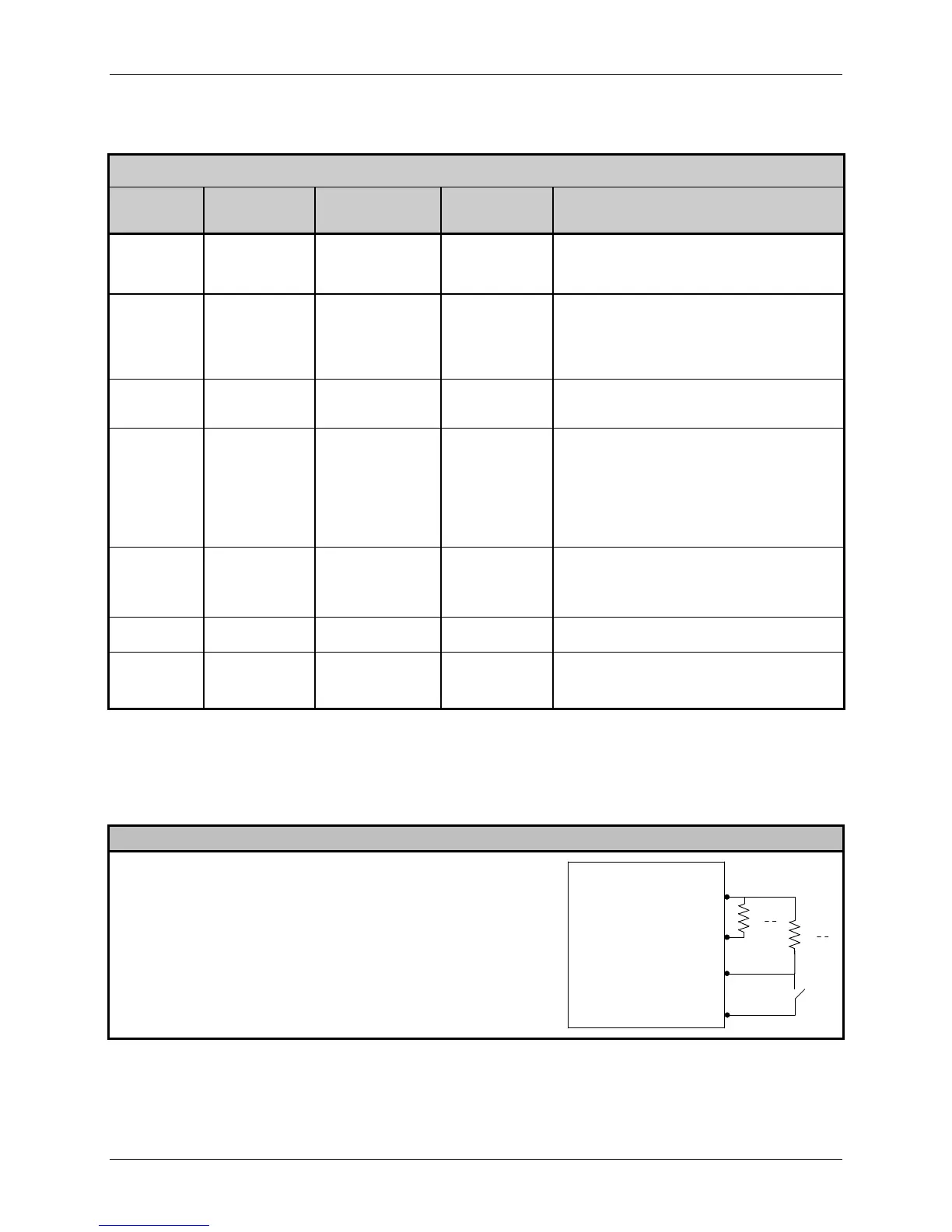
M-Class Sample SOP Circuit
Pin 3 should be pulled to +5VDC. In additional, connections for the
external Start of Print control can either be directly made to Pin 4 of
the Option Port (or via the Main CCA) using a TTL-level input, or
via an interface circuit (similar to the one shown).
1
8
Vcc
Gnd
GPIO Connector Pin Number
3Spare
4SOP
1K
O
1K
O