Appendix J – General Purpose Input Output Ports
Class Series Programmer’s Manual 229
I & W-Class GPIO
GPIO pin functions are detailed in the table below:
I-Class and W-Class GPIO Overview
Pin
Number
Signal
Name
Signal
State
Signal
Direction *
Description
1 Vcc +5 VDC Output +5 VDC power supply.
2 Ribbon Fault Low Output
Goes low when a ribbon out condition is
detected.
3Paper Fault Low Output
Goes low when an out of stock condition is
detected.
4 Printer Fault Low Output Goes low when any printer fault is detected.
5 Ribbon Low Programmable Output
Goes high (or low) when a low ribbon supply
is detected.
6 End of Print Programmable Output
Goes high (or low) when printing is complete,
typically monitored to initiate the next Start of
Print sequence.
7 Backup Label Programmable Input
When received, will position a presented label
for printing, provided that the programmed
present distance is greater than zero.
8
Start of Print
Signal (SOP)
Programmable
Input
When received, begins printing. (If the printer
awaits the SOP signal, WAITING FOR
SIGNAL will be displayed).
9 Signal Ground Ground N/A Ground return.
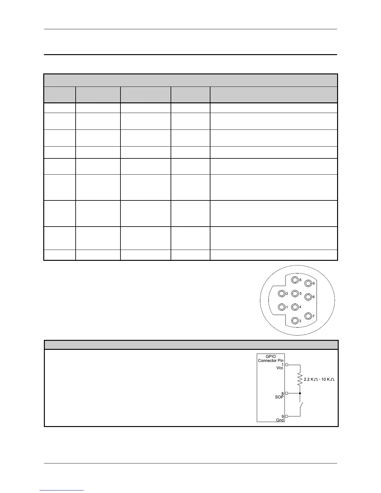
GPIO pin configuration (illustrated right), as viewed from the rear of the printer:
I-Class and W-Class Sample SOP Circuit
Connections for an external Start of Print/Backup Label control can be made (1)
directly to Pin 8 / 7 using a TTL-level input or (2) with an interface circuit similar
to the one shown right. For additional interfacing requirements, see the table
above.